
In short
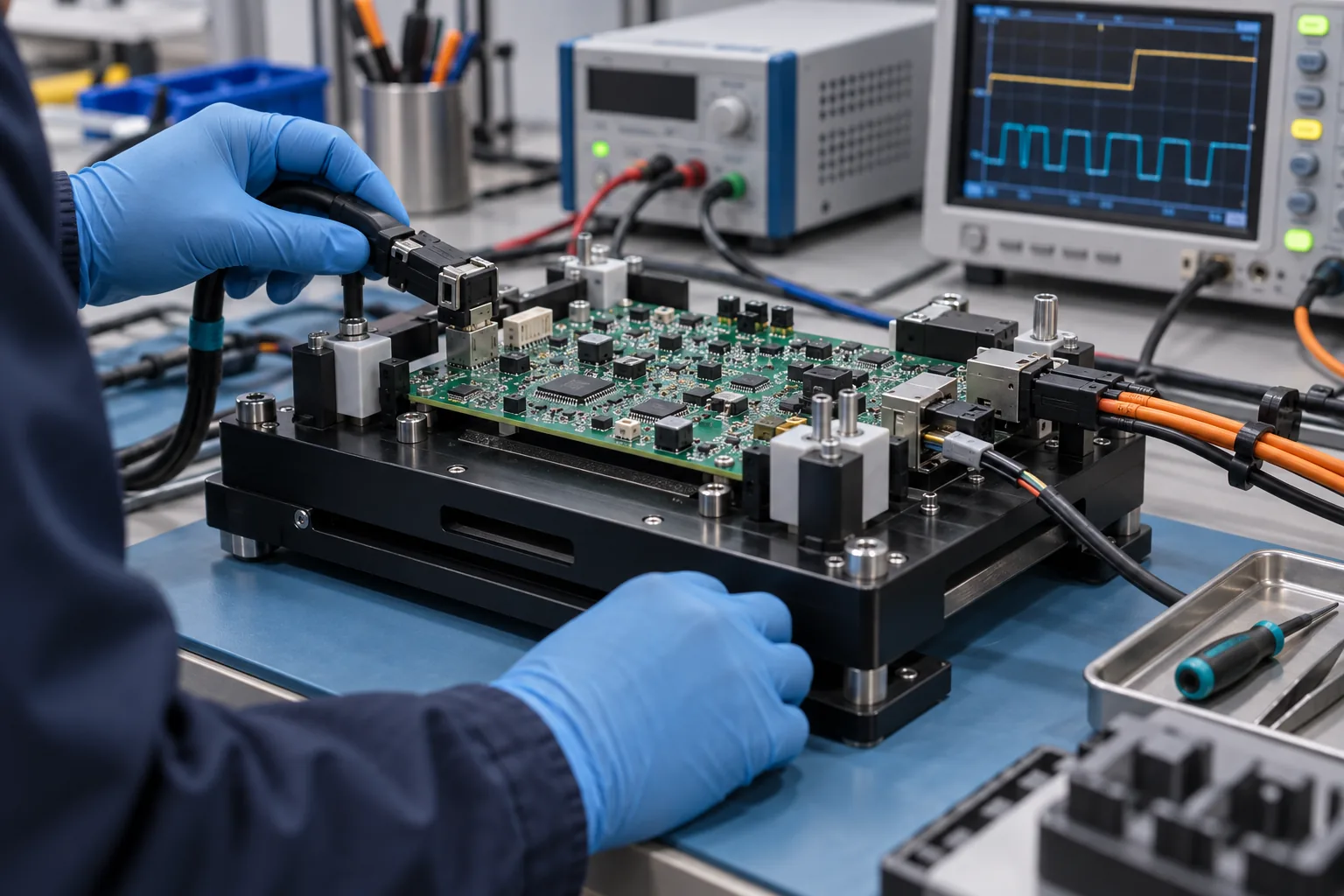
Start a PCBA functional-test fixture with a testable behavior list, not a photo of the board. Identify the DUT revision, safe power sequence, connector map, loads, firmware, communications, stimuli, measured outputs and pass/fail limits. Keep fixture hardware, cable set and test software under separate version IDs, then record the exact combination used for every pilot result.
- Define each required behavior as stimulus, condition, measurement, unit, limit and failure action.
- Separate fixture mechanics, cable/interface assemblies, instruments, firmware and test software into versioned items.
- Use final connectors for product behavior where practical; use probe access only for the internal nodes the test truly needs.
- Pilot records must identify DUT, BOM/assembly, firmware, fixture, cables, software, limits and result—not only PASS.
Write the fixture brief as a map from product behavior to a repeatable test setup. Name the DUT revision, connector pinout, safe power sequence, loads, firmware, communication settings, stimuli, measurements and pass/fail limits. Give fixture hardware, cable assemblies and test software separate version IDs. A pilot unit is useful only when its result can be traced to the exact board, program, fixture and limits that produced it.
What inputs are required before functional-test fixture development?
Provide the current product definition plus an executable test list. The minimum package includes schematic, BOM, assembly and mechanical data, connector pinouts, power-tree information, firmware/programming files, interface protocols, required loads or simulated peripherals, safety constraints and a step-by-step list of observable behaviors. For every measurement, state the condition, point, unit, lower and upper limit and what happens after a failure.
| Input group | What to provide | Question it closes |
|---|---|---|
| DUT identity | PCBA number/revision, variant, assembly drawing, BOM and mechanical envelope. | Which physical and electrical product is being tested? |
| Interfaces | Connector, pinout, mating part, communication mode and signal direction. | How does the fixture contact and communicate with the DUT? |
| Power and loads | Supply rails, current limit, sequence, discharge, loads and isolation. | How can the DUT be energized without masking a fault or causing damage? |
| Software | Firmware image, configuration, programmer, test sequence and dependencies. | Which code and state make the expected behavior valid? |
| Acceptance | Stimulus, measurement point, unit, limits, timing and failure action. | What exactly produces PASS or FAIL? |
| Records | Unit ID, timestamp, versions, measured values, failure code and retest history. | Can the pilot result be repeated and compared later? |
How should DUT interfaces, power, loads and communications be defined?
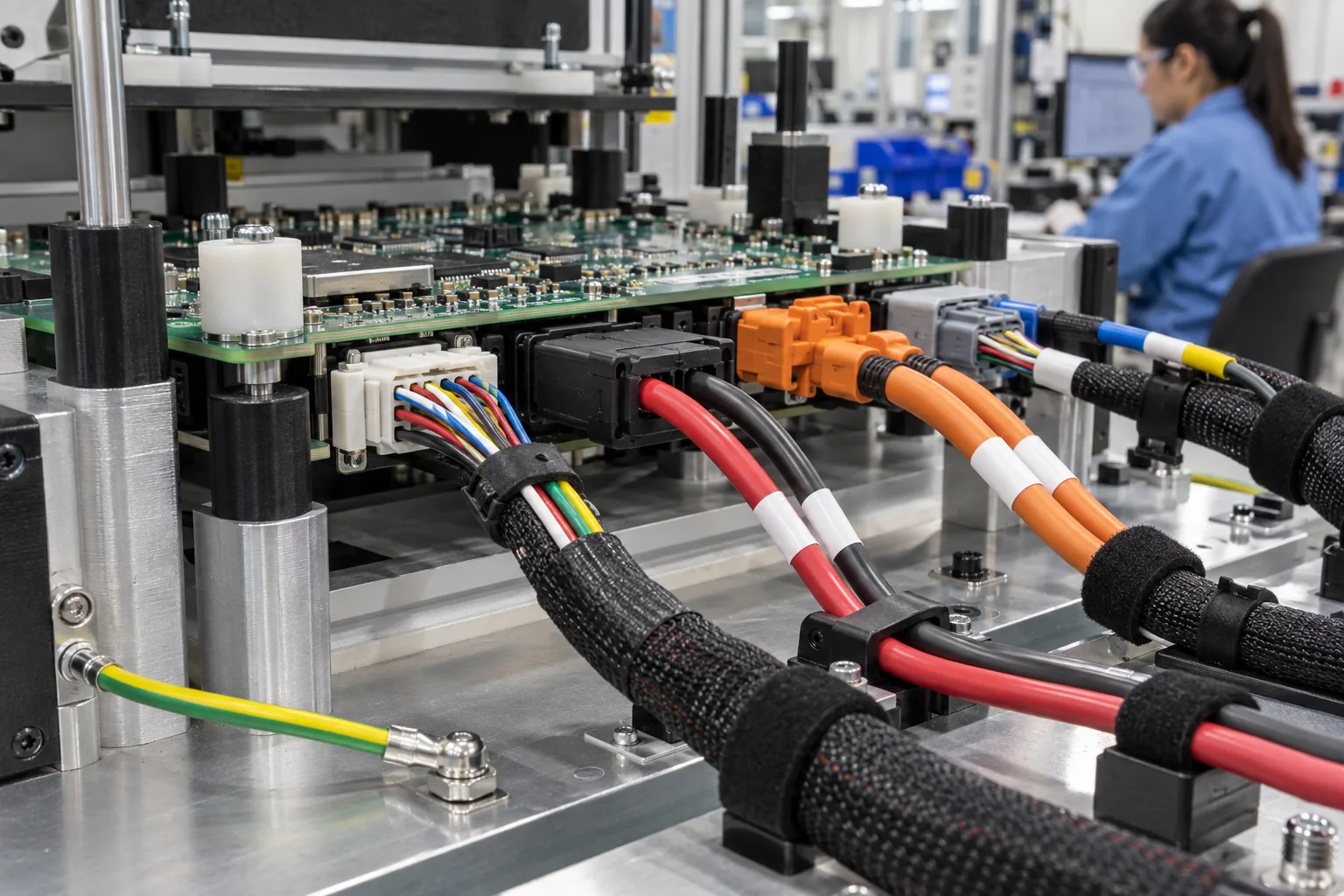
Define every interface by pin, direction, electrical state and test purpose. For a connector, name the mating part or controlled adapter, pin map, keying, insertion method and cycle-life concern. For power, state nominal input, current limit, polarity protection, sequencing, settling time and a safe way to remove stored energy. For a load or simulated peripheral, identify operating modes and tolerances rather than writing “connect normal load.”
Communication tests need protocol, physical layer, address, bitrate, termination, command, expected response and timeout. Analog measurements need point, reference, bandwidth or settling condition, unit and limits. Digital I/O needs pull state, drive level and whether the fixture stimulates, observes or both. These details turn a functional claim such as “USB works” into a repeatable operation.
How do fixture, test program, cables and product versions stay matched?
Give each item its own revision and store their approved combination in a compatibility table. The fixture mechanical assembly can change without a software change; a cable pinout can change without moving the DUT; firmware can change expected messages or timing without altering the board. One shared label such as “FCT v2” hides those differences.
| Item | Version identity | Compatibility field | Change that requires review |
|---|---|---|---|
| DUT | PCB/PCBA part, revision and variant | Supported fixture/cable/program set | Connector, rail, I/O, component or mechanical change |
| Fixture hardware | Fixture assembly and wiring revision | DUT envelope and access map | Locator, support, probe, interlock or wiring change |
| Cable/interface set | Cable part and pinout revision | Connector and signal assignment | Mating part, wiring, shielding or load change |
| Test software | Application and sequence revision | Limits file, instrument setup and DUT firmware | Step, command, timing, calculation or limit change |
| DUT firmware | Image/configuration ID and checksum | Expected protocol and behavior | Boot, interface, calibration or output change |
How is functional test different from ICT, flying probe and programming?
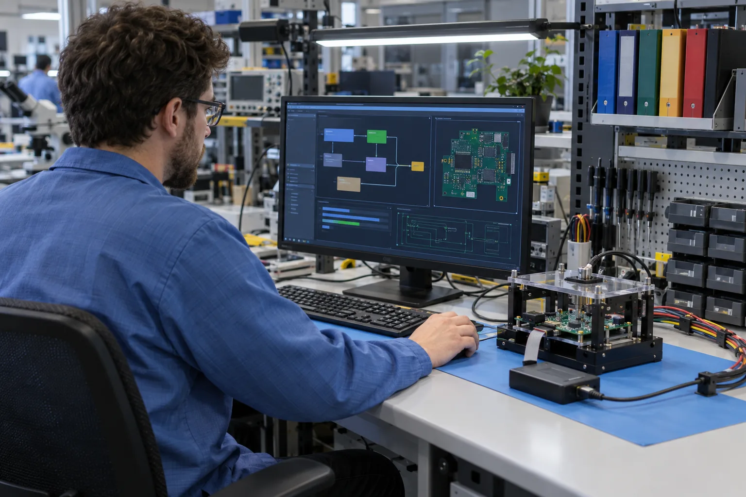
Functional test demonstrates only the powered behaviors the sequence exercises. ICT and flying probe focus on accessible structural or component-level electrical checks and can help localize assembly faults. Programming writes or verifies device code or data. A fixture may combine operations, but combining hardware does not make their evidence interchangeable.
| Operation | Primary question | Typical input | What it does not prove alone |
|---|---|---|---|
| ICT | Are selected accessible nets/components structurally correct? | Fixture, netlist, targets, program and limits. | Complete end-use behavior. |
| Flying probe | Do selected reachable nets/components meet programmed checks? | CAD/netlist, coordinates, access and program. | Inaccessible features or all product functions. |
| Programming | Was the intended image/data written and verified? | Device, interface, image, configuration and verify method. | That every hardware function operates. |
| Functional test | Does the DUT perform the specified behavior under stated conditions? | Power, interfaces, firmware, stimuli, loads and limits. | Untested behavior or every possible assembly defect. |
What results should a PCBA pilot build record?
Record enough context to reproduce a result, not only PASS or FAIL. Capture the unit serial or pilot ID, PCB/assembly revision and variant, BOM deviation status, DUT firmware/configuration, fixture and cable revisions, test-software/sequence and limits versions, instrument identity when measurement traceability matters, timestamp, operator or station, measured values, failure code, retest history and final disposition.
Keep the first failures. A pilot is where connector seating, fixture alignment, power sequencing, limit selection and software timing are most likely to change. Deleting early runs erases the information needed to separate a fixture problem from a product problem. Mark invalid setup runs explicitly instead of rewriting them as product passes.
What should the copyable fixture brief say?
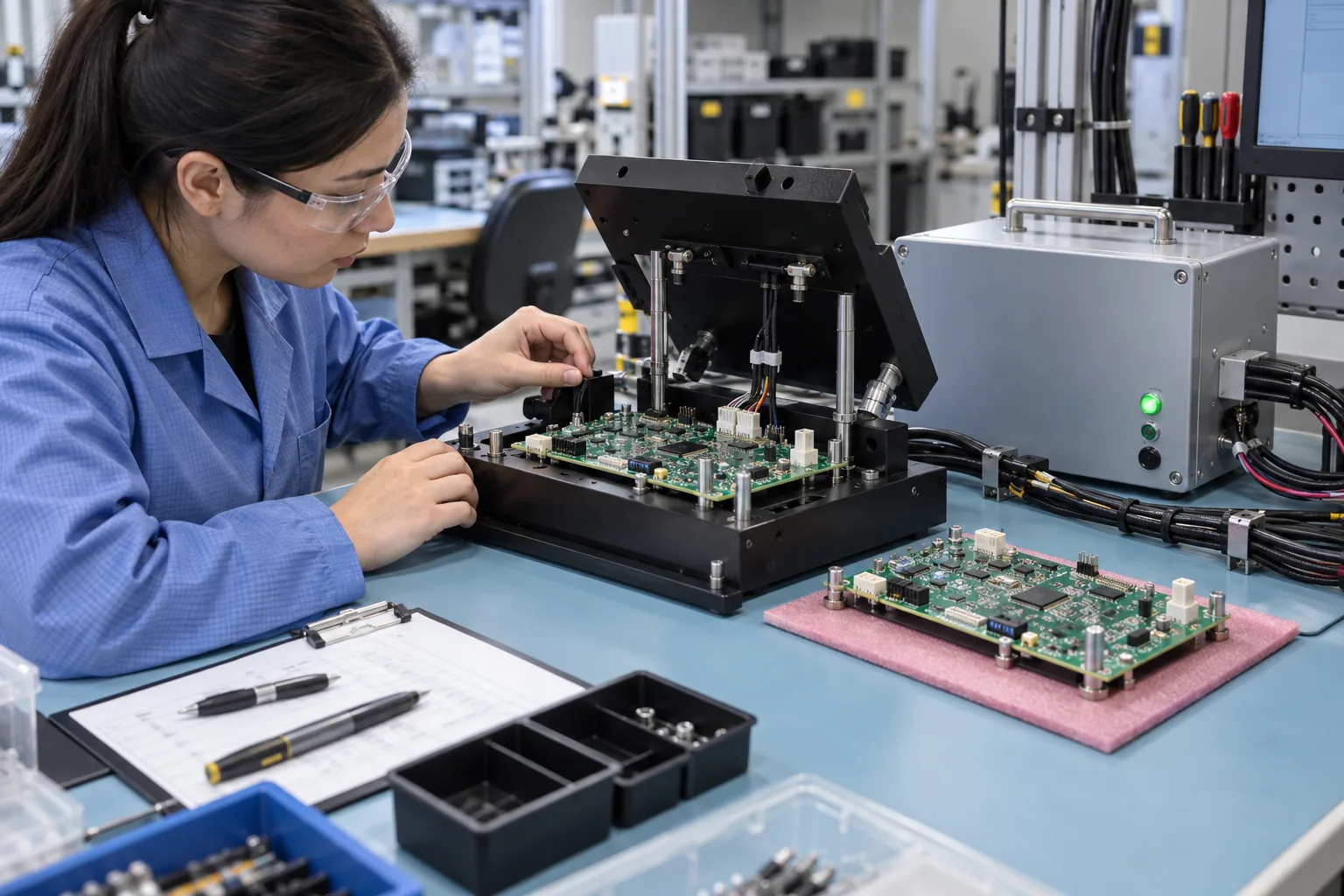
Use one line per test behavior and one version table for the complete setup. Avoid phrases such as “test all functions” or “normal limits.” They do not define an instrument action or an acceptance decision.
Fixture brief example: “DUT: [part/revision/variant]. Interface: [connector/pin map/cable rev]. Apply [input] with current limit [value] and sequence [steps]. Load [output] with [load/mode]. Install firmware/configuration [ID/checksum]. Stimulate [condition]. Measure [point/parameter] after [settling/time window]. PASS when [lower limit] ≤ [value and unit] ≤ [upper limit]. On FAIL: remove power safely, record [code/value], and route to [diagnostic action]. Record fixture, cable, software, limits and firmware revisions with the unit result.”
How should the pilot fixture be validated before repeat production?
Challenge the setup with known conditions and repeat the mechanical and electrical sequence. Verify connector keying, board seating, support, interlocks, current limiting, discharge and operator access. Run a known reference state plus deliberate open, wrong-connection or limit-boundary conditions that the fixture can safely simulate. Confirm that a repeated good unit produces stable measured values and that a known failure is reported by the intended step.
The outcome is a compatible set of fixture, cables, test software, firmware and limits, plus an unresolved-issue list. It is not a universal coverage percentage. Use the test-point design guide for internal access and the method comparison when a structural test should complement FCT. For a project-specific route, connect the finished brief to PCB assembly testing.
About the author
PCBArise Electronics
PCBArise Electronics publishes this guide to help design and NPI teams prepare clearer manufacturing files. The requirements for any actual build are confirmed from its current design package.
FAQ
Common questions
What is required to design a PCBA functional-test fixture?+
Provide the DUT part/revision and mechanical data, schematic and pinouts, safe power sequence, loads or simulated peripherals, firmware/configuration, communication settings, required stimuli and measurements, pass/fail limits, result format and expected build quantity.
Should a functional-test fixture use product connectors or PCB test points?+
Use product connectors when the goal is to verify end-use interfaces and mating behavior. Add probe or internal access only for power sequencing, programming, diagnosis or measurements that final connectors cannot expose. Document both paths in the interface map.
Is programming the same as functional test?+
No. Programming writes or verifies code or data in a device. Functional test then exercises defined powered behavior. They may share a station, but each needs its own input, version identity and result.
What should a pilot-build functional-test result contain?+
Record unit ID, PCB/PCBA revision and variant, firmware/configuration, fixture and cable revisions, test software and limits versions, test conditions, measured values, pass/fail, failure code, retest history and final disposition.
How do you validate a PCBA functional-test fixture?+
Check seating, connectors, support, wiring, safety and power removal; run a known reference condition; exercise safe known failures or limit boundaries; repeat the same unit to assess stability; and publish the exact compatible hardware, software, firmware and limits set.
Technical references
Sources used for this guide
These sources explain the standards, materials or process details discussed above. Check the current revision when applying them to a new design.
- NI — mass interconnect and fixturing fundamentals
- Keysight — separating structural probing from functional test
- Keysight — fixture and probe integrity checks
- APTPCB — functional-test input and reporting context
- GoPCBA — current fixture-design considerations
- GÖPEL electronic — 2026 test and programming system announcement