
Stencil and paste
Set aperture strategy, stencil thickness and paste family from pad geometry, package mix and thermal demand.
Need surface-mount assembly for a prototype or repeat order? PCBArise plans stencil printing, placement, reflow, inspection and testing around your board layout, component packages and build quantity.
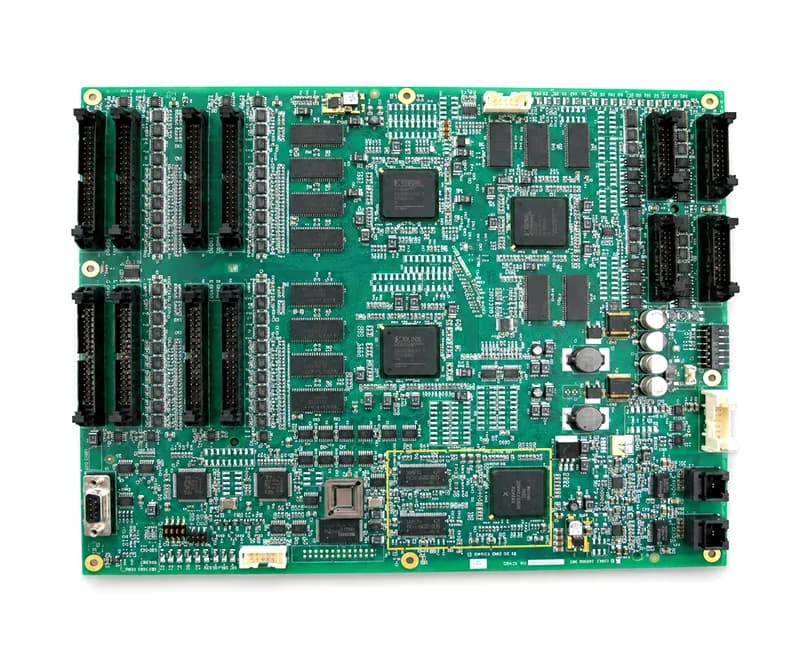
For hidden solder joints, review placement and inspection in the BGA assembly overview.
SMT assembly places surface-mount components onto a printed circuit board through a controlled print, placement and reflow process. Feasibility depends on the package mix, land patterns, board construction, thermal limits and the inspection or test evidence required for the build.
Fine-pitch results depend on the whole print-to-reflow chain. The package library, pad design, stencil, board support and inspection method should be reviewed as one system.
Set aperture strategy, stencil thickness and paste family from pad geometry, package mix and thermal demand.
Resolve rotation, polarity, origin and package-library mismatches before the program reaches the line.
Define the profile around component limits, board mass, finish and solder alloy instead of applying one generic recipe.
Sequence secondary-side SMT, selective soldering or hand operations so later steps do not disturb earlier joints.
This reference describes the data and process controls needed for a credible quotation. Exact package, pitch, panel and board limits are confirmed after file review.
Use this as a quotation checklist; exact package, pitch, panel, inspection and test limits require the released files.
| Quote inputs | Gerber or ODB++, BOM, CPL/centroid data, assembly drawing and available test requirements |
|---|---|
| Package review | Chip, leaded, bottom-terminated and array packages evaluated against land pattern and inspection access |
| Board construction | Rigid, flex or rigid-flex assembly reviewed for support, handling and thermal exposure |
| Solder system | Lead-free or leaded route selected by product requirement and approved material set |
| Stencil strategy | Aperture, thickness and stepped-stencil needs reviewed from the package mix |
| Reflow control | Profile established for assembly thermal mass, components and solder-paste requirements |
| Inspection | SPI, AOI, X-ray or manual methods selected where they can detect the defined risks |
| Test interface | ICT, flying-probe, programming or functional test supported when fixtures, limits and procedures are available |
The CAD, BOM, fabrication data and drawing must describe the same design revision. A technically clean SMT launch resolves mismatched designators, polarized parts, do-not-populate positions and special handling before material is released.
The quote and build plan become meaningful only when the assembly package is internally consistent.
Use the process when compact component density, repeatable automated placement or double-sided assembly drives the build.
Dense digital and mixed-signal control boards with defined programming and functional checks.
Assemblies with shielded areas, array packages and impedance-sensitive board construction.
Low-volume and repeat builds where revision control and traceability matter as much as placement.
Quality documents
The published ISO records name Zhongshan Wenquan Electronic Manufacturing Co., Ltd. and its Zhongshan PCBA facility. They do not certify every PCBArise facility, service or product.


These are management-system certificates, not product or batch COAs. No batch inspection reports or COAs are currently published here.
Use these SMT answers to prepare the placement package and identify process controls that still need engineering review.
Provide fabrication data, BOM, CPL or centroid data, assembly drawings and the available test or programming requirements. A mismatch between those files is resolved before the build route is confirmed.
Fine-pitch and array packages can be evaluated. Feasibility depends on the land pattern, stencil strategy, board construction, component availability and the inspection access required for that design.
No. Inspection is selected from the package and defect risks. SPI, AOI, X-ray, manual inspection and electrical or functional testing each cover different failure modes.
The schedule is confirmed after file consistency, material availability, process route, fixture needs and the inspection or test plan have been reviewed.
Move from surface-mount process questions to capability, prototype, turnkey and material decisions with the existing Assembly pages.
Share fabrication data, BOM, CPL, drawings and the available inspection or test requirements with the PCBArise team.