
Patient monitors, vital-sign monitoring, bedside displays and alarm electronics
Industries / PCB & PCBA
Medical PCB & PCBA Manufacturer
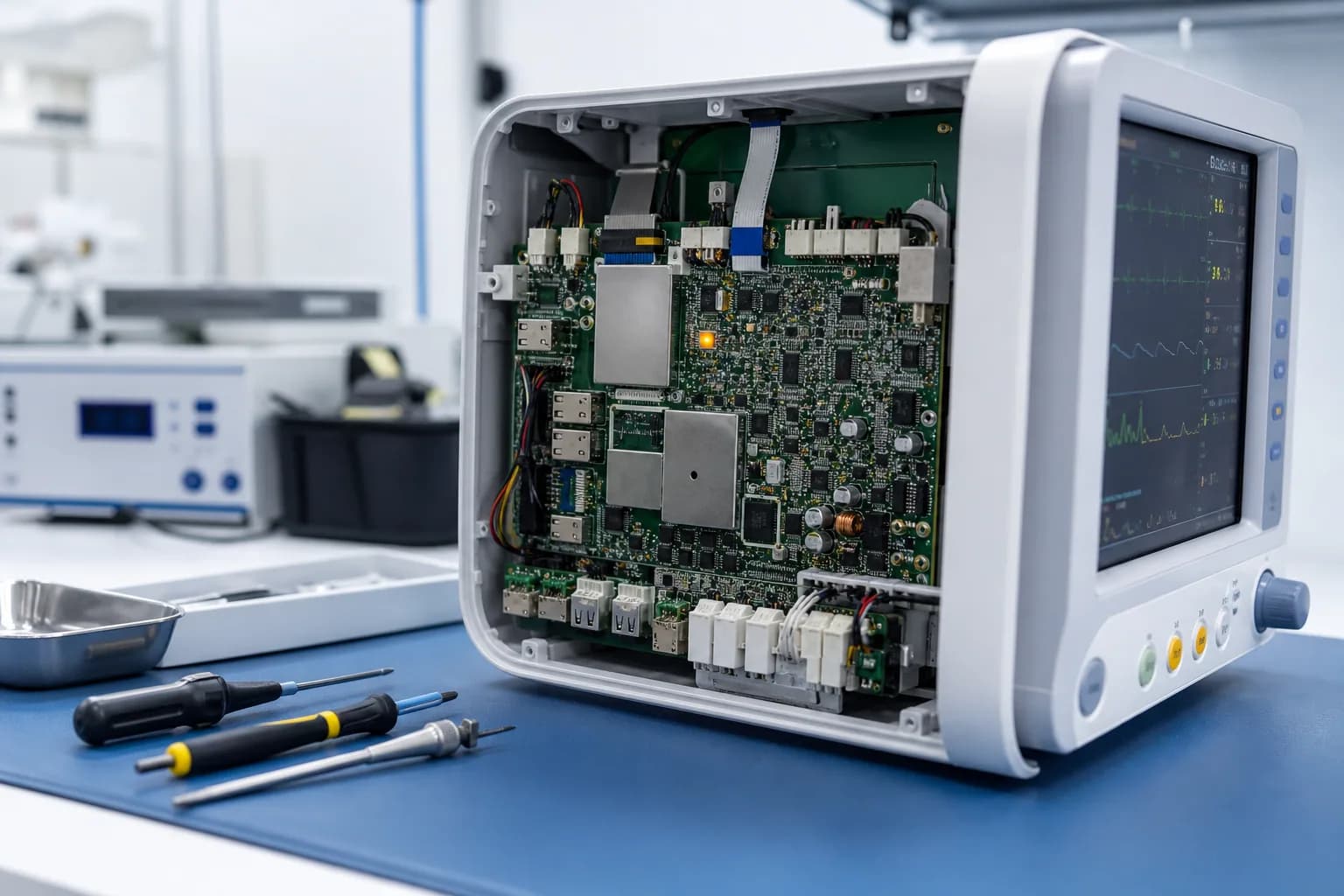
PCBArise provides medical PCB assembly and manufacturing support for patient monitors, diagnostic instruments, laboratory analyzers, medical sensors, portable healthcare devices and therapy controllers. The device role, patient-contact boundary, released drawing, inspection plan, traceability and documentation package are confirmed with the assigned facility before quotation.
Project-specific scopeIPC Class 2 / Class 3Project TraceabilityInspection Plan Review

Product usePatient Monitor, Diagnostic & Medical Sensor PCB ApplicationsChosen for your product
Board constructionMedical Monitor and Diagnostic PCB Construction
Assembly routeMedical PCB Assembly for Monitors, Sensors & Analyzers
Quality checksMedical PCB Quality & Device Evidence
Typical applications
Patient Monitor, Diagnostic & Medical Sensor PCB Applications
Medical PCB buyers need the board and assembly scope to match the finished product requirements. We start with what the board does inside the monitor, analyzer, sensor or therapy device, then define the PCB and PCBA route around the released requirements.
Diagnostic instruments, laboratory analyzers and sample-handling controls
Medical sensor, signal-conditioning and data-acquisition boards
Portable healthcare, battery-management and charging electronics
Ultrasound, imaging and medical-instrument control boards
Therapy, rehabilitation and clinical-equipment controller assemblies
Engineering choices
What Medical PCB Buyers Need to Qualify
Medical electronics are judged by repeatability, documentation and product risk—not only by whether a prototype powers on. PCBArise builds the released PCB and PCBA scope with agreed evidence while the medical-device manufacturer remains responsible for the finished device and regulatory obligations.
Patient-monitor and diagnostic sensor channels need clean analog references, isolation and controlled interfaces
Long-life clinical equipment needs component identity, lot traceability and controlled substitutions
Cleanliness, coating and enclosure interfaces can affect leakage, insulation and sensor stability
Fine-pitch processors, analog front ends, HDI and rigid-flex need a defined inspection and rework plan
Prototype changes must move into approved production data without undocumented drift
The required quality-system evidence is scoped to the manufacturing entity and project records, not a finished-device approval
Board and process options
Medical Monitor and Diagnostic PCB Construction
The patient-monitor, analyzer or sensor design determines stackup, isolation, signal integrity and density. Standard and advanced PCB windows are considered against the released medical product and its documentation scope.
Product focus
Medical electronics need evidence that matches the released device scope.
Patient monitoring, diagnostic and laboratory products are reviewed around electrical safety, traceability, documentation and the applicable quality-system scope.
- ISO 13485 scope reviewed per project
- Patient-contact and safety requirements
- Inspection, records and change control
Medical Instrument PCB Construction Review
Capability values to confirm against isolation, signal, cleanliness and device documentation needs
| Parameter | Specification |
|---|---|
| Layer Count | 1–40 Layers |
| Base Material | FR-4, High-Tg FR-4, halogen-free FR-4, Rogers, Taconic/AGC, PI, aluminum, PTFE/Teflon, F4B and other specialty laminates |
| Board Thickness | 0.10–10.0 mm |
| Controlled Impedance | ±10% standard; ±5% for tighter requirements |
| Warpage | ≤0.75% standard; ≤0.5% available when specified |
| Surface Finishes | HASL, Lead-Free HASL, OSP, ENIG, Immersion Silver, Immersion Tin, ENEPIG, Hard Gold, Gold Finger and selective finishes |
Board and process options
Medical Sensor, HDI & Mixed-Signal Options
Diagnostic and monitoring boards often combine fine-pitch processors, analog front ends, controlled impedance and compact sensor routing. HDI, rigid-flex, material and stackup decisions are confirmed against the device role and acceptance plan.
Product focus
Medical electronics need evidence that matches the released device scope.
Patient monitoring, diagnostic and laboratory products are reviewed around electrical safety, traceability, documentation and the applicable quality-system scope.
- ISO 13485 scope reviewed per project
- Patient-contact and safety requirements
- Inspection, records and change control
Medical Sensor, HDI & Mixed-Signal Review
Advanced options selected only where the released medical electronics design requires them
| Parameter | Specification |
|---|---|
| Min Laser Microvia | 0.075 mm |
| Controlled Impedance | ±10% standard; ±5% for tighter requirements |
| HDI Structures | 1+N+1, 2+N+2, multi-step HDI and Any-Layer HDI |
| Via Technology | Blind vias, buried vias, stacked vias, staggered vias, via-in-pad, VIPPO / POFV, resin-filled and plated-over vias |
| Warpage Control | ≤0.5% available when specified, subject to stack-up and design review |
| Board Thickness Tolerance | ±0.05 mm |
Assembly considerations
Materials for Patient Monitoring & Diagnostic Electronics
Material, finish, solder mask, cleanliness and coating choices follow the electrical safety, sensor, thermal, mechanical and documentation requirements of the released medical product.
Options to discuss
Start with what your design needs.
We can confirm the workable combination after reviewing your files.
FR-4High-Tg TG170RogersPIRigid-FlexENIGENEPIGOSPImmersion TinConformal Coating
What to send
Choose for the product you are building.
- ISO 13485 scope reviewed per project
- Patient-contact and safety requirements
- Inspection, records and change control
Board and process options
Medical PCB Assembly for Monitors, Sensors & Analyzers
Fine-pitch processors, sensors, connectors and mixed-technology content are assembled against the approved BOM, drawings, workmanship class and inspection plan for the monitor, analyzer or healthcare device.
Product focus
Medical electronics need evidence that matches the released device scope.
Patient monitoring, diagnostic and laboratory products are reviewed around electrical safety, traceability, documentation and the applicable quality-system scope.
- ISO 13485 scope reviewed per project
- Patient-contact and safety requirements
- Inspection, records and change control
Medical Electronics Assembly Window
Placement and soldering values reviewed with the approved BOM, cleanliness and inspection plan
| Parameter | Specification |
|---|---|
| Min Component Size | 01005 (0.4 × 0.2 mm) |
| Min BGA Pitch | 0.25 mm |
| Min QFP / QFN Pitch | 0.15 mm spacing / 0.3 mm width |
| Placement Accuracy (X/Y) | ±0.025 mm (±25 μm) |
| Warpage Control | ≤0.5%(Subject to board construction and assembly process review) |
| Soldering Methods | Wave Soldering, Selective Soldering, Hand Soldering |
How the board fits the product
Medical electronics need evidence that matches the released device scope.
Patient monitoring, diagnostic and laboratory products are reviewed around electrical safety, traceability, documentation and the applicable quality-system scope.
- ISO 13485 scope reviewed per project
- Patient-contact and safety requirements
- Inspection, records and change control
Project-specific scopeIPC Class 2 / Class 3Project TraceabilityInspection Plan Review
Inspection, testing and records
Medical PCB Quality & Device Evidence
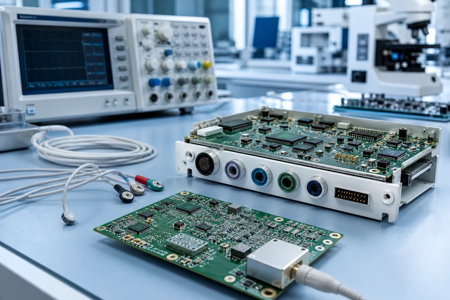
The evidence package may include DFM/DFA, incoming inspection, SPI, AOI, X-ray, electrical test, traceability, nonconformance review and production documentation. Required certificates, quality-system scope and records are confirmed for the manufacturing entity and project before award; they do not certify a finished medical device or replace the product owner’s regulatory responsibilities.
ISO 9001:2015ISO 14001:2015IPC-A-600IPC-A-610Project-specific declarations
Build files
Keep the board revision, BOM and assembly drawings together so the factory builds the intended configuration.
Inspection and test
Choose optical, X-ray, electrical or functional checks for the defects that matter to this product.
Material tracking
Agree which material and production records you need to retrieve after shipment.
Design changes
Decide who can approve a material, component or process change before it reaches the line.
Quality documents
Preview & download certificates
The published ISO records name Zhongshan Wenquan Electronic Manufacturing Co., Ltd. and its Zhongshan PCBA facility. They do not certify every PCBArise facility, service or product.


These are management-system certificates, not product or batch COAs. No batch inspection reports or COAs are currently published here.
Frequently asked questions
Common questions about this PCB application
Start with the board, environment and files you have; the detailed route depends on your design.
How do you confirm quality-system evidence for a medical PCB or PCBA project?
Before award, PCBArise confirms the assigned manufacturing entity, requested certificate scope, released drawing, inspection plan, traceability requirements and documentation package. Any manufacturing-system evidence applies to the agreed production scope; it does not mean the finished medical device is certified by the PCB supplier.
What medical electronics can you build?
Typical projects include patient monitors, diagnostic instruments, medical sensors, laboratory equipment, portable healthcare electronics, therapy controllers, and imaging or ultrasound control boards. We assess the electrical, mechanical, cleanliness, coating, and documentation requirements before quotation.
How do you handle traceability for medical PCBA?
Traceability is defined against the project requirements and can link the approved BOM, component lots, inspection records, test results, process records, and shipment release documentation. The exact record set is agreed before production rather than assumed from a generic page claim.
Can you assemble low-noise medical sensor and diagnostic boards?
Yes. We review stackup, grounding, isolation, impedance, cleanliness, coating, component placement, and the required electrical or functional test before release. Mixed-signal, fine-pitch, HDI, rigid, and rigid-flex constructions are evaluated against the released files.
Do you provide medical-device regulatory approval?
No. PCBArise supplies PCB and PCBA manufacturing support and agreed production records; the medical-device manufacturer remains responsible for product design, risk management, regulatory submissions, and finished-device approvals. We can review the manufacturing evidence your quality system requires.
What should I send for a medical PCB quotation?
Send Gerber or ODB++ files, BOM, pick-and-place data, assembly drawings, stackup or impedance requirements, inspection and test procedures, workmanship class, coating or cleanliness requirements, traceability expectations, and any applicable customer quality questionnaire or NDA.
Related PCB pages
Explore the board and assembly options behind this product.
Use the related PCB, PCBA and quality pages to plan the next part of your build.
PCBArise resource
Certification Scope
Published ISO records and the project-specific evidence request process.
PCBArise resourceQuality Control
Inspection, testing, documentation, and project traceability controls.
PCBArise resourcePCB Assembly Capabilities
SMT, THT, mixed-technology assembly, inspection, and testing.
PCBArise resourceHDI PCB
Compact high-density construction for medical instrumentation.
PCBArise resourceDFM Review
Review medical PCB files and acceptance requirements before release.
Start a medical electronics PCB scope review.
Send the released design, device classification, documentation requirements and quality expectations for review.