
Switch-mode power supply, AC-DC and DC-DC converter boards
Industries / PCB & PCBA
Power Electronics PCB & PCBA Manufacturer
PCBArise manufactures power PCB and power supply PCB/PCBA for power supplies, inverter PCBs and motor-drive stages, IGBT/MOSFET modules, UPS, welding equipment, LED drivers and high-current industrial systems. Buyers start with current, voltage, thermal interface and assembly mass; those product requirements determine whether the board uses heavy copper, metal core, ceramic or a mixed power-and-control construction.
0.5–12 oz CopperUp to 3.0 W/m·K0.1–10.0 mm Thickness1–40 Layers
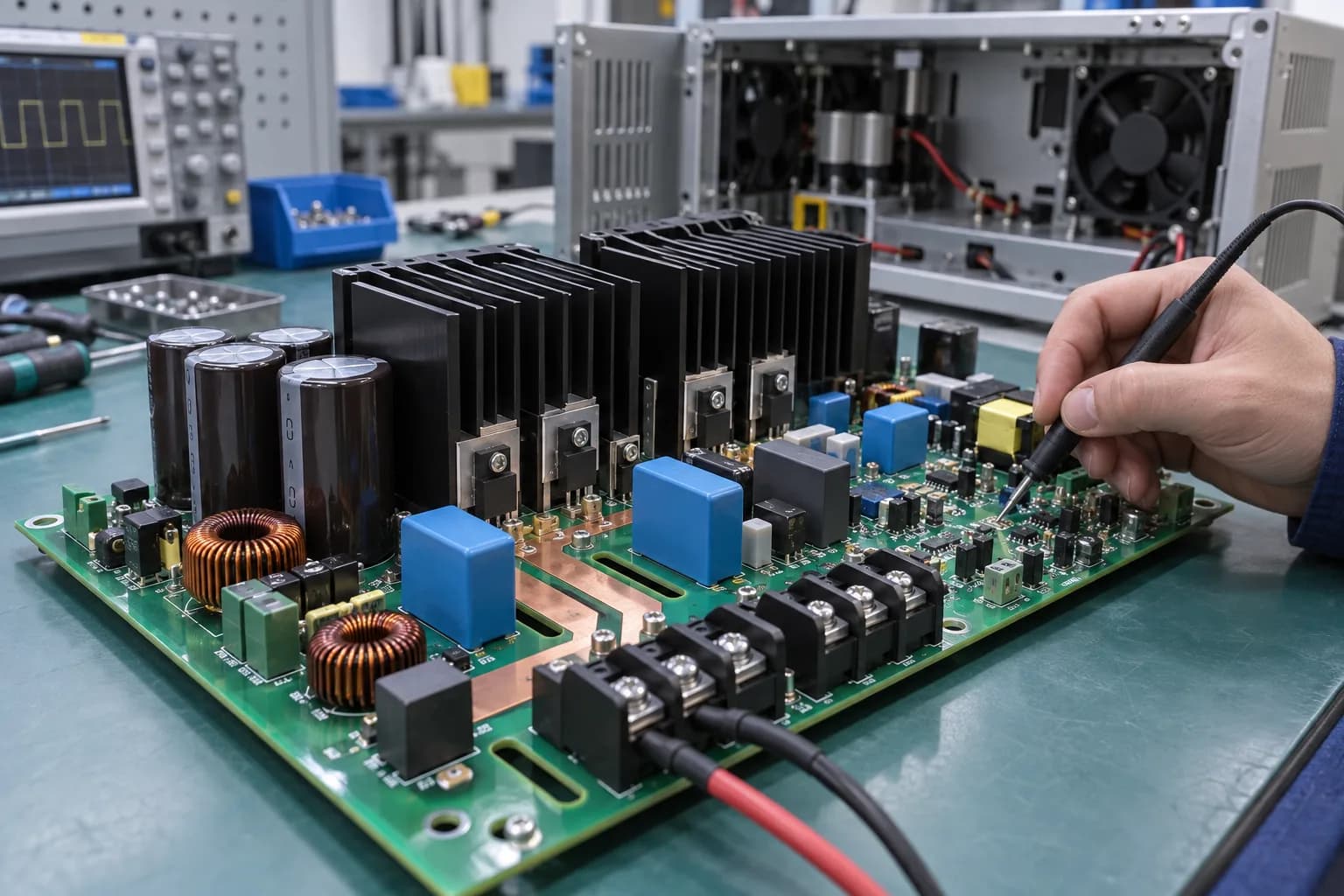
Product usePower Supply, Inverter & Motor-Drive PCB ApplicationsChosen for your product
Board constructionHeavy-Copper and Thick-Copper PCB for the Actual Power Path
Assembly routePower PCBA for IGBT, Busbar & Motor-Drive Assemblies
Quality checksPower Electronics Quality, Thermal Evidence & Test
Typical applications
Power Supply, Inverter & Motor-Drive PCB Applications
Power electronics buyers search for a board partner around the power stage they are releasing. We connect the application—power supply, inverter, motor drive, IGBT, LED or UPS—to the PCB construction, assembly method and test access.
Inverter, motor-drive and variable-frequency-drive power stages
IGBT, MOSFET, gate-driver and isolated power-interface assemblies
Industrial rectifier, UPS, battery charger and power-distribution boards
High-power LED lighting and metal-core thermal boards
Welding, induction-heating, servo and high-current machine-control electronics
Busbar-style power interfaces and mixed power/control backplanes
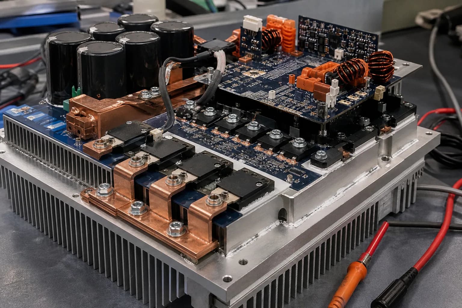
Engineering choices
What Power Electronics PCB Buyers Need to Decide
A power electronics PCB supplier must understand the complete power path, not only the routed artwork. Current, voltage, switching frequency, heat flow, isolation and component mass all affect the manufacturable product.
Continuous current and temperature rise: copper weight, plane width and connector rating are sized for the real load
Thermal path: chassis contact, heat spreader, thermal vias, aluminum or ceramic substrate and component placement work together
High-voltage isolation: creepage, clearance, slotting, coating and cleanliness belong in the product review
Mixed geometry: heavy-copper power planes sit beside fine-line gate-drive, sensing and communication circuitry
Power cycling: plated-through holes, large solder joints and interfaces are checked against the service profile
Assembly mass: transformers, inductors, electrolytics, heatsinks and busbars determine soldering and fixture access
Board and process options
Heavy-Copper and Thick-Copper PCB for the Actual Power Path
The converter, inverter or motor-drive requirement sets copper and stackup. The standard production window covers 0.5–12 oz copper and 1–40 layers; engineering checks the current path, isolation areas and mixed control geometry before tooling.
Product focus
Power density makes material, copper and assembly choices inseparable.
Power boards combine current-carrying geometry, thermal paths, high-mass components and control circuitry. The build route has to protect all of them together.
- Copper weight and heat spreading
- Thermal interface and substrate choice
- THT, selective solder and inspection access
Standard PCB Specifications
Volume production capabilities for rigid and multilayer PCB
| Parameter | Specification |
|---|---|
| Layer Count | 1–40 Layers |
| Base Material | FR-4, High-Tg FR-4, halogen-free FR-4, Rogers, Taconic/AGC, PI, aluminum, PTFE/Teflon, F4B and other specialty laminates |
| Board Thickness | 0.10–10.0 mm |
| Min Trace Width / Spacing | 2.5 / 2.5 mil (0.0625 / 0.0625 mm) |
| Min Mechanical Drill | 0.15 mm |
| Min Laser Via | 0.10 mm |
| Standard Aspect Ratio | Up to 15:1 |
| Copper Thickness | 0.5–12 oz, depending on board type and construction |
| Min BGA Pad Diameter | 8 mil |
| Controlled Impedance | ±10% standard; ±5% for tighter requirements |
| Warpage | ≤0.75% standard; ≤0.5% available when specified |
| Surface Finishes | HASL, Lead-Free HASL, OSP, ENIG, Immersion Silver, Immersion Tin, ENEPIG, Hard Gold, Gold Finger and selective finishes |
Board and process options
Inverter, IGBT & Motor-Drive Thermal Options
When an inverter or IGBT stage must transfer heat into the chassis, aluminum PCB reaches thermal conductivity up to 3.0 W/m·K; ceramic is considered for higher power density. The control-side routing, gate drive and sensing geometry are reviewed at the same time.
Product focus
Power density makes material, copper and assembly choices inseparable.
Power boards combine current-carrying geometry, thermal paths, high-mass components and control circuitry. The build route has to protect all of them together.
- Copper weight and heat spreading
- Thermal interface and substrate choice
- THT, selective solder and inspection access
Advanced Multilayer & HDI PCB
R&D prototyping and high-end HDI builds
| Parameter | Specification |
|---|---|
| Layer Count | Up to 64 Layers(Prototype / engineering builds) |
| Min Trace Width / Spacing | 2 / 2 mil (0.05 / 0.05 mm) |
| Standard Mechanical Drill | 0.15 mm |
| Advanced / Special Hole Capability | Down to 0.10 mm, subject to design and process review |
| Min Laser Microvia | 0.075 mm |
| Aspect Ratio | Up to 20:1 for qualified designs; 15:1 or below for standard advanced production |
| Controlled Impedance | ±10% standard; ±5% for tighter requirements |
| HDI Structures | 1+N+1, 2+N+2, multi-step HDI and Any-Layer HDI |
| Via Technology | Blind vias, buried vias, stacked vias, staggered vias, via-in-pad, VIPPO / POFV, resin-filled and plated-over vias |
| Sequential Lamination | Supported |
| Any-Layer Interconnection | Supported |
| Back Drilling | Supported |
| Warpage Control | ≤0.5% available when specified, subject to stack-up and design review |
| High-Speed / High-Frequency Materials | Rogers, Taconic/AGC, PTFE/Teflon, F4B, High-Tg FR-4 and other low-loss specialty laminates |
| Board Thickness Tolerance | ±0.05 mm |
| Thermal Conductivity | Up to 3.0 W/m·K(Aluminum PCB) |
Assembly considerations
Materials for Power Supplies, Inverters & LED Drivers
Aluminum, ceramic, High-Tg FR-4, copper weight and surface finish are selected for the product’s power density, thermal interface, voltage isolation, solderability and lifecycle—not as a generic process menu.
Options to discuss
Start with what your design needs.
We can confirm the workable combination after reviewing your files.
AluminumCeramicHigh-Tg TG170FR-4RogersTeflonLead-Free HASLENIGImmersion TinOSPHard GoldHeavy Copper
What to send
Choose for the product you are building.
- Copper weight and heat spreading
- Thermal interface and substrate choice
- THT, selective solder and inspection access
Assembly considerations
Power PCBA for IGBT, Busbar & Motor-Drive Assemblies
Power PCBA combines transformers, inductors, electrolytics, IGBT/MOSFET devices, busbars and heatsinks with an SMT control section. The assembly route—SMT, THT, selective or hand soldering, coating, inspection and functional test—follows the actual power module and enclosure. Review the full PCBA process envelope on the PCB Assembly Capabilities page before selecting the route.
- Mixed-technology assembly for SMT control sections and through-hole power components
- Odd-form, press-fit, wave, selective and hand-soldering options evaluated by joint geometry
- Assembly support, thermal mass, clearance and test access confirmed from the released package
What to send
Choose for the product you are building.
- Copper weight and heat spreading
- Thermal interface and substrate choice
- THT, selective solder and inspection access
Assembly considerations
Power-Stage Assembly and Integration Scope
Options to discuss
Start with what your design needs.
We can confirm the workable combination after reviewing your files.
Mixed-Technology AssemblyTHT / DIP AssemblyOdd-Form ComponentsPress-FitWave SolderingSelective SolderingHand SolderingMetal-Core PCB AssemblyConformal CoatingCable & Harness AssemblyBox Build
What to send
Choose for the product you are building.
- Copper weight and heat spreading
- Thermal interface and substrate choice
- THT, selective solder and inspection access
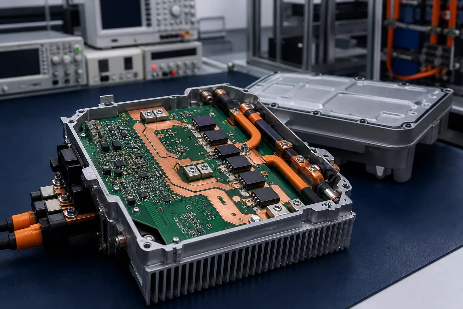
How the board fits the product
Power density makes material, copper and assembly choices inseparable.
Power boards combine current-carrying geometry, thermal paths, high-mass components and control circuitry. The build route has to protect all of them together.
- Copper weight and heat spreading
- Thermal interface and substrate choice
- THT, selective solder and inspection access
0.5–12 oz CopperUp to 3.0 W/m·K0.1–10.0 mm Thickness1–40 Layers
Inspection, testing and records
Power Electronics Quality, Thermal Evidence & Test
The quality plan follows the power product: current and thermal assumptions, isolation, component lots, solder joints, X-ray or electrical test, functional limits and the records required for repeat production. Heavy copper and metal-core risks are reviewed before tooling; IPC-A-600/A-610 class and acceptance remain project-specific.
ISO 9001:2015ISO 14001:2015
Build files
Keep the board revision, BOM and assembly drawings together so the factory builds the intended configuration.
Inspection and test
Choose optical, X-ray, electrical or functional checks for the defects that matter to this product.
Material tracking
Agree which material and production records you need to retrieve after shipment.
Design changes
Decide who can approve a material, component or process change before it reaches the line.
Quality documents
Preview & download certificates
The published ISO records name Zhongshan Wenquan Electronic Manufacturing Co., Ltd. and its Zhongshan PCBA facility. They do not certify every PCBArise facility, service or product.


These are management-system certificates, not product or batch COAs. No batch inspection reports or COAs are currently published here.
Frequently asked questions
Common questions about this PCB application
Start with the board, environment and files you have; the detailed route depends on your design.
How much copper can a power PCB or thick copper PCB use?
The published reference covers 0.5–12 oz copper. Copper weight is selected against your current and allowable temperature rise. Note that heavy copper etches with a trapezoidal profile, so achievable trace width and spacing widen as copper weight increases — our engineers confirm the achievable geometry for your copper weight during project DFM review rather than assuming the standard 2.5/2.5 mil minimum applies.
What thermal conductivity can your aluminum PCB reach?
Aluminum PCB reaches thermal conductivity up to 3.0 W/m·K. For higher power density we also manufacture ceramic substrate. Which one is right depends on your junction temperature target and the mechanical interface to the chassis — send us the thermal requirement with your RFQ and engineering will come back with a recommendation.
How thick a board can you build and assemble?
Fabrication supports 0.1–10.0 mm board thickness, with 1.6 mm standard and a thickness tolerance of ±0.05 mm on advanced builds. The published PCBA assembly thickness and warpage envelope applies to the relevant assembly route and must be confirmed against board construction and process review.
Can you handle large power boards and tall components?
The PCBA capability reference publishes a 50 × 50 mm to 400 × 1200 mm assembly envelope and a 120 mm maximum component height for applicable process lines. Board support, tooling, clearance and the soldering route are confirmed during engineering review. Wave, selective and hand soldering are available for high-thermal-mass and odd-form joints.
Can you build a board with heavy copper power planes and fine-line control circuitry together?
Yes, and it is one of the more common reasons power boards fail DFM elsewhere. The constraint is copper balance and resin fill during lamination. We review copper balance, stackup, and prepreg selection before tooling and will propose a build that holds both the current requirement and the control-side geometry.
What is the lead time for a heavy copper power board?
For 4–6 layer multilayer PCB: 48–72 hours prototype, 4–6 days small batch, 8–10 days mass production. Heavier copper and metal core builds typically sit at the longer end of the range. All lead times are subject to final evaluation of production files, process complexity, and BOM availability.
Related PCB pages
Explore the board and assembly options behind this product.
Use the related PCB, PCBA and quality pages to plan the next part of your build.
PCBArise resource
Thermal PCB Design Inputs
Compare heavy-copper, metal-core and complete heat-path inputs before releasing the build route.
PCBArise resourcePCB Materials & Stackup
Aluminum, ceramic, and High-Tg options with stackup design support.
PCBArise resourcePCB Manufacturing Capabilities
Full fabrication specifications, materials, and process limits.
PCBArise resourceEV & Energy PCB
EV charging, BMS, and renewable energy power conversion boards.
PCBArise resourceIndustrial Control PCB
PLC, motor drive, and factory automation boards.
PCBArise resourceDFM Review
Free manufacturability review before production starts.
Turn the power requirement into a buildable PCB package.
Share current, temperature, thermal-interface and mechanical requirements with the PCBArise engineering team.