

In short
A PCB DFM review looks beyond CAD design-rule checks to the manufacturing package. Before requesting a quote, collect the fabrication data, stackup, material and finish requirements, drill and outline details, BOM, placement data, drawings and relevant test access. Put one revision on the package and resolve open design questions with the manufacturer.
A useful PCB manufacturing quote starts with a design package that tells the fabricator and assembler what to build. CAD DRC is a good first check; DFM adds the intended stackup, materials, holes, board edges, component placement and test access. Reviewing these inputs before quoting reduces assumptions and makes supplier feedback actionable.
Use this checklist before opening a project review. It makes missing decisions visible and assigns each DFM finding to an owner. PCBArise can review released project data through its DFM review pathway, but the final construction, process, schedule and evidence are confirmed for the actual package rather than implied by a generic checklist.
Fabrication DFM, assembly DFM and testability answer different questions
Fabrication DFM asks whether the bare-board definition can be produced through the assigned process route. It looks at the relationship between stackup, materials, copper geometry, holes and vias, solder mask, surface finish, board outline and panel intent. The relevant question is not whether a feature meets a universal number; it is whether the released feature set is compatible with the selected construction and process.
Assembly DFM asks whether the components and assembly definition can be placed, soldered, inspected and reworked as intended. BOM identity, approved alternates, footprints, pad and paste definitions, polarity, placement rotation, fiducials, component spacing, board-edge access and thermal constraints belong here. Review the available PCB assembly route separately from the bare-board decision.
Design for test asks whether the planned inspection or electrical test can reach the required features and prove the required behavior. Test points, connectors, fixture access, programming state, conditions and pass/fail limits are product inputs. They are not automatically created by a fabrication or assembly DFM check.

Files to check before requesting a PCB quote
| Review lane | Inputs to confirm | Question the package must answer | Typical owner |
|---|---|---|---|
| Stackup and impedance | Layer order, overall thickness, material intent, copper by layer, reference planes, target impedance and tolerance where applicable | Is electrical intent tied to a construction the manufacturing team can review? | PCB designer with fabrication engineering input |
| Copper and holes | Trace/space, copper-to-edge, finished holes, plated versus non-plated holes, slots, via types, fill/cap or backdrill requirements | Are finished requirements distinguishable from tool or artwork dimensions? | PCB designer |
| Outline and panel | Closed board profile, dimensions, tolerances, routing or scoring intent, rails, tooling, breakaway and keep-outs | Is the delivered unit or customer panel unambiguous? | Mechanical/PCB owner with NPI |
| Assembly data | BOM, manufacturer part numbers, approved alternates, reference designators, Pick & Place, assembly drawings and variant state | Do part identity, footprint and placement records describe the same revision? | Design owner and sourcing/NPI |
| Polarity and orientation | Pin-one marks, diode/capacitor polarity, connector orientation and bottom-side rotation conventions | Can an assembler reconcile the drawing, silkscreen, footprint and placement file? | PCB/assembly owner |
| Test and evidence | Probe or connector access, firmware state, fixtures, conditions, limits and required records | What must the build demonstrate, and what evidence is required? | Product/test owner |
| Release control | Board and assembly part numbers, revision, variant, file manifest, approval state and change contact | Does every released file belong to one approved configuration? | Configuration owner or NPI |

Fabrication DFM: stackup, holes and outline
Stackup, material and impedance intent
State whether the stackup is fixed, preferred or open to manufacturer proposal. Include the layer order, finished thickness, copper requirements and controlled-impedance targets where they apply. If a trace geometry was calculated around a particular dielectric construction, keep that relationship visible. A fabrication team may propose a manufacturable stackup, but the design owner must confirm that the proposal still meets electrical intent.
Copper, holes and board profile
Check the features that depend on real process tolerances: trace and space, annular rings, drill-to-copper relationships, finished hole sizes, plated versus non-plated status, slots, microvias, via fill/cap, backdrill and copper near routed or scored edges. Supply a machine-readable closed outline and make special edge plating, castellations or cut-outs explicit. The PCB manufacturing page describes available board routes, but project limits still depend on the released construction.
Panel and handling intent
Do not leave panelization as an unlabeled drawing layer. State whether the quote is for individual boards, a customer-defined array or manufacturer panelization. Identify rails, fiducials, tooling holes, breakaway method, component keep-outs and any dimension that the delivered array must meet. This lets the quotation distinguish customer-controlled geometry from production tooling decisions.
Assembly DFM: BOM, placement and access
BOM, placement and variants
Use manufacturer part numbers where part identity matters, list approved alternates intentionally and keep reference designators consistent between BOM, placement data and assembly drawings. Remove do-not-fit references from the active variant or mark their status unambiguously. Verify bottom-side rotation conventions in the exported placement file instead of assuming the recipient uses the same convention as the design tool.
Footprints, spacing and polarity
Review footprint-to-part agreement, courtyard and body clearances, access around tall parts and connectors, paste definitions, thermal pads, fiducials and polarity marks. A design can be electrically correct while creating a placement, soldering, inspection or rework problem. The finding should identify the affected reference, the manufacturing concern and the released evidence used to resolve it.
Test points and product checks
List the intended inspection and test route only where it is part of the project. Identify probe pads or connectors, fixture constraints, programming requirements, power and load conditions, pass/fail limits and the record the product owner expects. Use the published quality-control pathway to frame the discussion, not to assume a fixed test plan or universal coverage.
DFM finding to release-decision table
| Finding type | Finding owner | Evidence needed | Release decision |
|---|---|---|---|
| Construction or impedance conflict | PCB design owner, supported by fabrication engineering | Proposed stackup or process response tied to the affected nets and revision | Approve the proposal, revise geometry/construction, or hold for clarification |
| Hole, clearance or outline conflict | PCB/mechanical design owner | Marked location, finished requirement and proposed correction | Revise and regenerate, or approve a documented project-specific disposition |
| Footprint, polarity or placement conflict | PCB/assembly design owner | Datasheet, approved footprint, BOM, placement and drawing agreement | Correct the source data or approve the controlled assembly interpretation |
| BOM or variant mismatch | Configuration owner with sourcing/NPI | Approved part/alternate list and active variant revision | Reconcile files before quote or state the pending commercial assumption |
| Test access or requirement gap | Product/test owner | Required behavior, access method, conditions, limits and record need | Add the requirement, change access, or remove unsupported scope explicitly |
| Revision mismatch | Configuration owner | One release manifest covering every delivered file | Stop and regenerate the package before quotation or build release |
The key control is ownership. A manufacturing engineer can explain process impact and suggest a route, but the customer/design authority approves changes to electrical, mechanical and product acceptance intent. A written finding is not closed until the agreed disposition is reflected in the controlled release package.
From CAD export to a quote-ready package
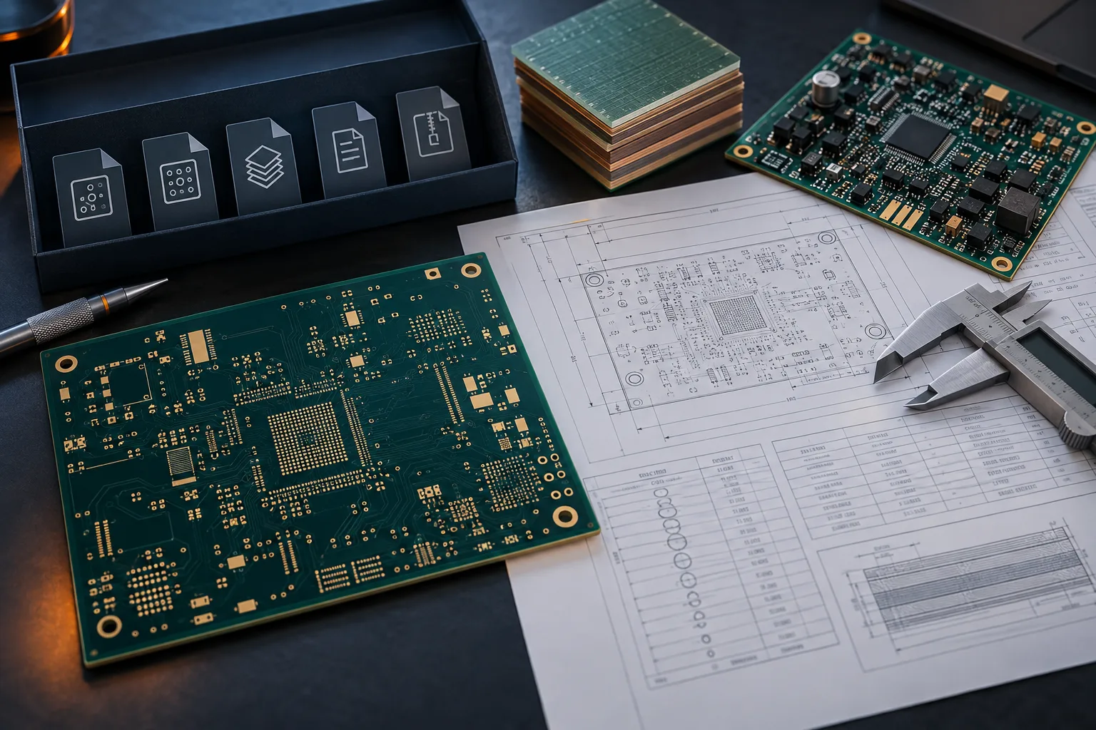
Start by naming the board, assembly variant and revision. Export the fabrication and assembly data from that approved state, then open the exact outputs independently. Review them against the intended process route. If a finding changes geometry, part identity, orientation, test access or acceptance, update the source and regenerate the package; do not patch one output while leaving the rest on an older revision.
Printable quote-ready checklist
Release identity
- □ Board and assembly part numbers, revision and active variant are named.
- □ One manifest lists the files included in the quote package.
- □ Old exports and duplicate versions are removed from the release archive.
Fabrication package
- □ Copper, mask, legend, paste where relevant, drill/route and closed board-profile data are present and aligned.
- □ Stackup, material, finished thickness, copper and impedance intent are documented where applicable.
- □ Finished holes, plated status, slots, special vias, board edges and panel intent are clear.
- □ Surface finish, solder-mask, marking and special fabrication notes match the current revision.
Assembly package
- □ BOM includes controlled part identity, reference designators and approved alternate rules.
- □ Pick & Place, assembly drawing, polarity and variant data agree with the BOM and PCB.
- □ Footprints, component spacing, fiducials, paste and access constraints have been reviewed for the intended route.
Test and decision package
- □ Inspection or test scope, access, setup, limits and required evidence are defined where requested.
- □ Each open DFM finding has an owner, a due decision and a visible quotation assumption.
- □ The design authority approves any change to functional, mechanical or acceptance intent.
Print this page or use the browser's Print to PDF option to support a design-freeze review. It is a release aid, not a substitute for project drawings, applicable requirements or the assigned manufacturing team's review.
What to send PCBArise
Send the current fabrication package plus BOM, Pick & Place, drawings and the test or acceptance requirements that are already defined. Include quantity, build stage and any open stackup, material, sourcing or panel decision. PCBArise can use those inputs to discuss a project-specific route and identify questions that affect scope; it cannot confirm the final DFM result without reviewing the released data.
FAQ
Common questions
What is the difference between fabrication DFM and assembly DFM?+
Fabrication DFM evaluates the bare-board construction, copper, holes, mask, outline and panel intent against a manufacturing route. Assembly DFM evaluates parts, footprints, paste, spacing, polarity, placement and access for soldering and inspection. A complete PCBA release may need both, plus a separate testability review.
Does passing CAD DRC mean a PCB is ready to quote?+
No. CAD DRC checks the rules configured in the design tool. A useful quote also needs a controlled output package and clear construction, assembly, test and revision inputs that can be reviewed against the receiving manufacturing route.
Which files should accompany a PCB or PCBA quote request?+
For fabrication, provide the released manufacturing data, drill/route and profile information, stackup and fabrication requirements. For assembly, add a controlled BOM, Pick & Place, assembly drawings, variant state and any test or programming requirements in scope.
Who decides how a DFM finding is resolved?+
Manufacturing engineering explains the process impact and proposed route. The customer or design authority approves changes to electrical, mechanical, part or acceptance intent, and the configuration owner makes sure the approved disposition appears in one controlled release package.
What can the design team check before sending files for DFM?+
Run the CAD design-rule check, inspect the exported Gerber or ODB++ layers and drill map, compare the board outline and stackup with the drawing, and reconcile BOM, placement data and assembly views to one revision. This catches internal contradictions before the fabricator checks the design against its manufacturing process.
Technical references
Sources used for this guide
These sources explain the standards, materials or process details discussed above. Check the current revision when applying them to a new design.