
In short
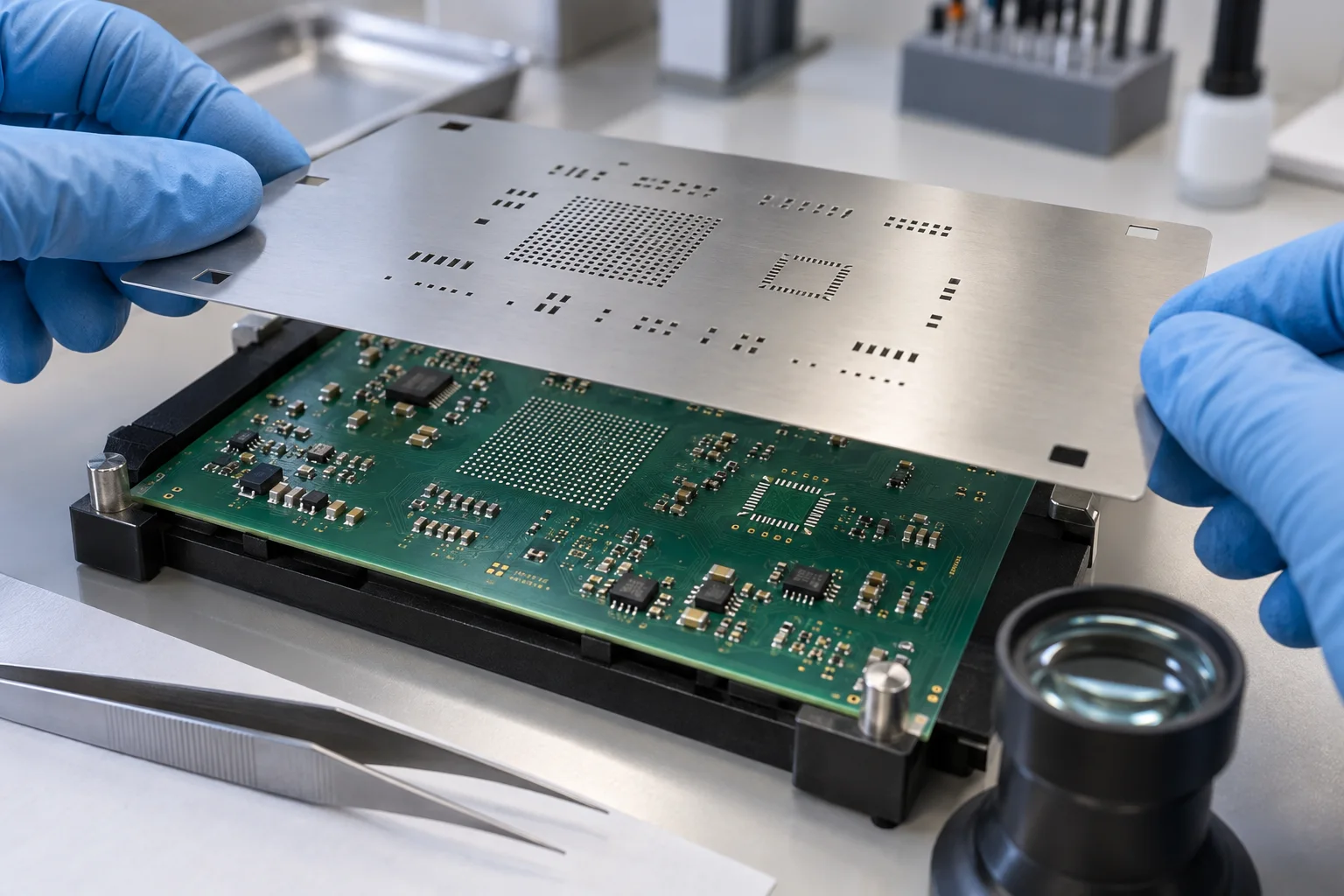
Do not apply one stencil-aperture reduction to every land. Begin with the component land pattern and the smallest printable opening, then test area ratio, foil thickness and paste release. BGA balls normally need consistent deposits across the array; QFN perimeter leads and its exposed thermal pad often need separate aperture treatment. Put the approved aperture geometry, foil thickness and print validation target in the assembly package.
- A stencil aperture controls deposited paste volume; it is not the same thing as solder-mask opening or copper-pad size.
- Check the smallest opening against foil thickness and paste-release geometry before copying a reduction rule across a board.
- Treat BGA ball lands, QFN perimeter terminals and a QFN exposed pad as three different solder-volume questions.
- State special apertures, foil thickness, paste and print-validation expectations in the released assembly package.
Set an SMT stencil aperture from the package land pattern, foil thickness and paste-release geometry—not from one board-wide shrink percentage. BGA lands, QFN perimeter pads and a QFN exposed thermal pad do different jobs during reflow. Start with the component supplier’s recommended land pattern, identify the smallest aperture, check its area ratio against the selected foil, then define any deliberate reduction or segmentation. This gives a design or NPI team a stencil file that explains the paste-volume decision instead of leaving the assembler to guess.
What changes in SMT stencil aperture design for BGA and QFN?
BGA apertures aim for repeatable deposits across an array; QFN apertures must separately manage small perimeter joints and the exposed thermal pad. A BGA ball brings its own solder sphere, so the objective is a uniform deposit that supports collapse and self-alignment without adding random volume variation. A QFN has perimeter terminals plus an underside center pad. Its perimeter openings must avoid bridges while still wetting the leads, and its large center land is commonly divided into smaller openings so paste is distributed rather than delivered as one solid brick.
Those are package-level starting points, not a license to copy a generic percentage. The component datasheet, pad geometry, surface finish, paste alloy, foil thickness, board stiffness and reflow profile all interact. Texas Instruments' QFN and BGA application material is useful because it ties aperture geometry to the actual package land pattern and paste-transfer limits. Use it with the selected component documentation rather than treating any one illustration as a universal library rule.
| Land group | Primary aperture question | What a poor choice can cause | Useful drawing output |
|---|---|---|---|
| BGA ball array | Will identical apertures release paste consistently across the smallest ball lands? | Insufficient or uneven deposits, solder balls or variable collapse. | Paste-layer geometry, foil thickness and a note identifying the BGA footprint revision. |
| QFN perimeter | Does the opening provide enough paste without crowding the adjacent lead? | Bridging, opens or a weak toe fillet after reflow. | Perimeter aperture dimensions linked to the package land pattern. |
| QFN exposed pad | Should the large opening be segmented to distribute paste and leave escape paths? | Excess solder, package float, voiding risk or unstable standoff. | Window-pane pattern, web geometry and paste-layer identifier. |
| Large connector or power pad | Can a larger opening retain the necessary area ratio while delivering the needed volume? | Under-print, incomplete release or too little solder for the joint. | Special aperture note rather than a silent paste-mask override. |
How do foil thickness and area ratio change the decision?
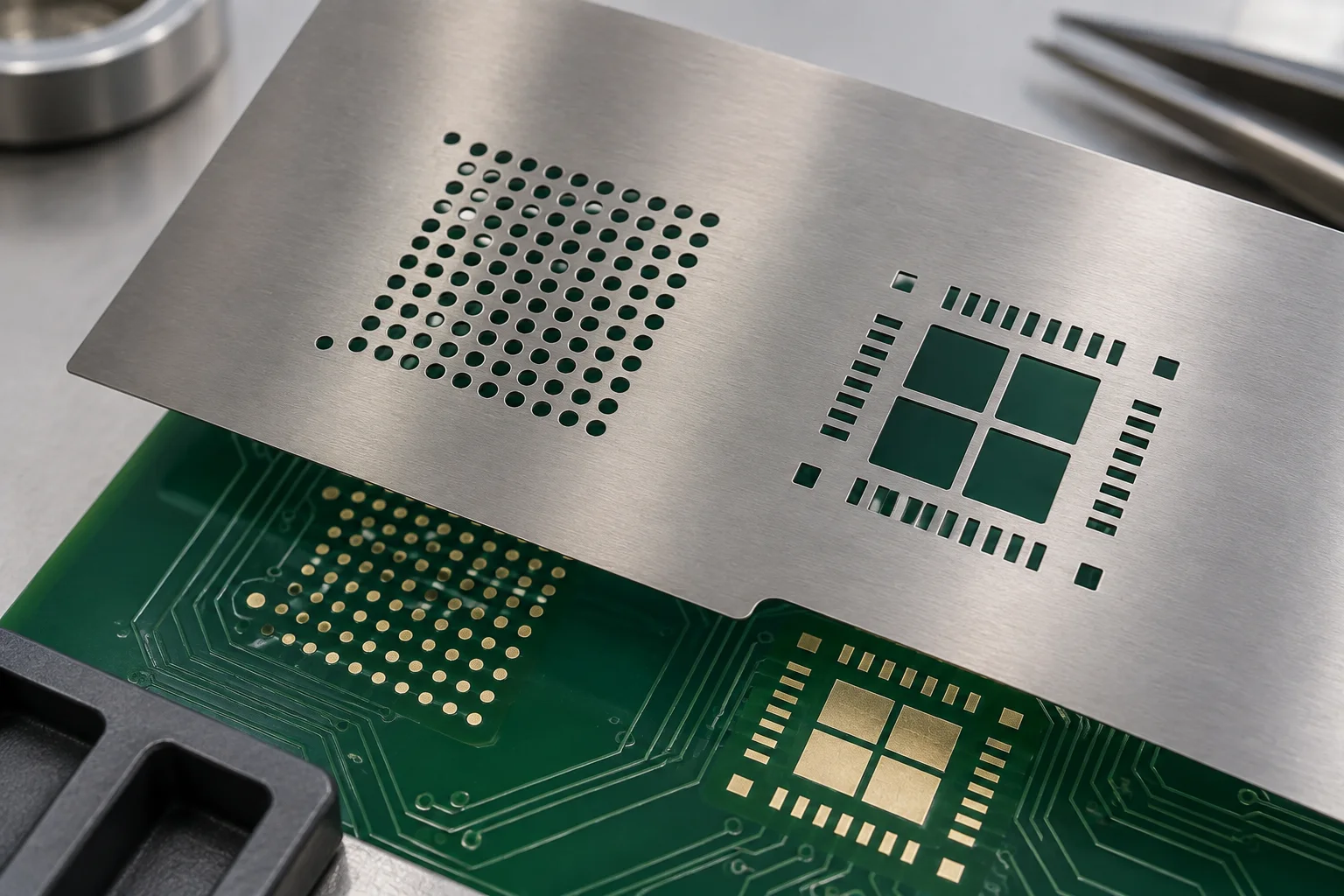
Use the smallest aperture and the foil thickness together to decide whether paste can release reliably. Area ratio compares the aperture opening area with the aperture-wall area. A smaller opening or thicker foil gives the paste more wall surface to cling to. IPC-7525 guidance is commonly summarized with an area-ratio target around 0.66, while Texas Instruments explains the same principle with package-specific examples. Treat that threshold as a screening tool: it tells you to investigate the print, not that every aperture above it is guaranteed to transfer perfectly.
For a rectangular opening, calculate from its actual length, width and foil thickness; for a round opening, use its actual diameter and thickness. Check the narrowest dimension, not only a large overall pad. A board with fine-pitch QFN leads may need a foil that permits those apertures to release, while larger pads elsewhere may need specially shaped openings to maintain their required deposit. That trade-off is why one thickness and one 1:1 rule cannot describe a mixed-density board.
Do not confuse area ratio with solder-mask clearance. Solder mask defines exposed pad area on the board. The stencil aperture defines the paste footprint above that pad. Changing mask expansion to solve a paste-volume problem can alter pad definition; changing an aperture to solve a mask-web problem can add bridges. Keep the two decisions on their correct layers and review them together at fine pitch.
When should a QFN thermal pad use a segmented opening?
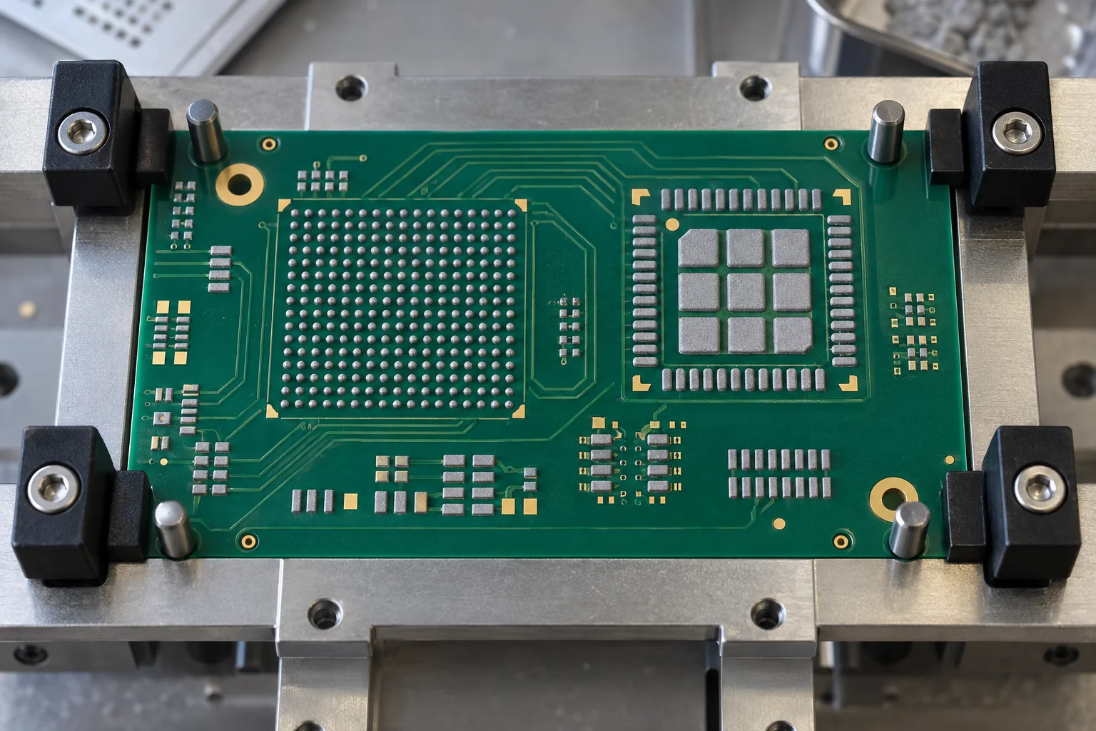
Segment an exposed-pad opening when one large paste deposit would deliver too much solder or provide no practical paths for paste and volatiles to escape during reflow. A window-pane pattern divides the thermal-pad deposit into smaller regions. It is often used to control total paste volume and reduce the tendency for a QFN to float on a large molten solder pool. The exact number, shape, web and coverage belong to the package documentation and the validated assembly process—not a generic “four windows” default.
Keep the thermal pad separate from the perimeter-lead decision. A QFN can have a well-behaved center deposit yet bridge at a perimeter opening, or have clean perimeter leads while the thermal pad produces unwanted stand-off or voiding. Review each group in the CAD paste layer, then compare print results before committing the footprint to a pilot build.
What should the assembly package say about a special aperture?
Show the aperture geometry in the paste layer and make the reason readable in the assembly notes. The manufacturer needs the actual CAD paste data, the board revision, stencil foil thickness, alloy or paste family when specified, and the component footprint source. If one footprint uses a reduction, home-plate shape, rounded corner or window-pane pattern, name the reference designator and the intended purpose. That stops a later library update from silently replacing a deliberate process choice.
Illustrative stencil note: “U4 QFN exposed pad uses the released segmented paste pattern in layer [name]. Keep the perimeter-pad apertures separate from the center-pad pattern. Stencil foil thickness: [value] mm. Check print coverage, deposit consistency and placement/reflow result on the pilot revision before copying this footprint to other assemblies.”
Fill the brackets from the real component documentation and process plan. The note does not claim a site-wide process or a fixed reduction. It tells a buyer and assembler exactly which CAD feature is intentional and what must be observed at the first print.

Four stencil-aperture mistakes that create avoidable reflow problems
- Using pad size as the only input: aperture dimensions also need foil thickness and paste-release geometry.
- Applying one reduction to BGA, QFN and connectors: each land group has a different solder-volume and spacing problem.
- Making the QFN center aperture one large block: consider a documented segmented pattern when the package guidance and validation support it.
- Leaving a special paste layer unexplained: identify the footprint, foil and pilot check so a later edit does not undo the reason for the shape.
Use the SMT assembly and BGA assembly pages for service context. The released paste layer, component land pattern and first-print review—not a generic stencil headline—are what make the aperture decision usable.
About the author
PCBArise Electronics
PCBArise Electronics publishes this guide to help design and NPI teams prepare clearer manufacturing files. The requirements for any actual build are confirmed from its current design package.
FAQ
Common questions
Should BGA stencil apertures be smaller than the pads?+
Start with the component supplier’s land-pattern and stencil guidance, then check aperture release with the selected foil thickness. A BGA needs consistent deposits across its array, but there is no safe universal reduction because ball pitch, pad size, paste and foil geometry change the result.
Why does a QFN thermal pad use window-pane stencil apertures?+
A segmented pattern can distribute paste across the exposed pad instead of making one large deposit. That helps control total solder volume and can reduce the chance of package float or trapped voiding. The final pattern must match the actual QFN documentation and validated print/reflow route.
What is stencil area ratio?+
Area ratio compares the opening area with the aperture-wall area. As an opening becomes smaller or foil becomes thicker, paste is more likely to stick to the walls instead of transferring to the pad. Use it to screen the smallest aperture before releasing a foil thickness.
Can solder-mask expansion fix a stencil aperture problem?+
No. Solder mask controls the exposed board pad; the stencil controls paste deposited over that pad. Altering mask expansion changes the pad definition, while altering an aperture changes paste volume. Review both at fine pitch, but correct the problem on the layer that causes it.
What files are needed for an SMT stencil review?+
Provide the released PCB and paste layers, BOM, placement data, assembly drawing, component land-pattern source, board revision, requested foil thickness and notes for any BGA, QFN or special aperture. Include the first-print or pilot check you need to make before the footprint is reused.
Technical references
Sources used for this guide
These sources explain the standards, materials or process details discussed above. Check the current revision when applying them to a new design.