
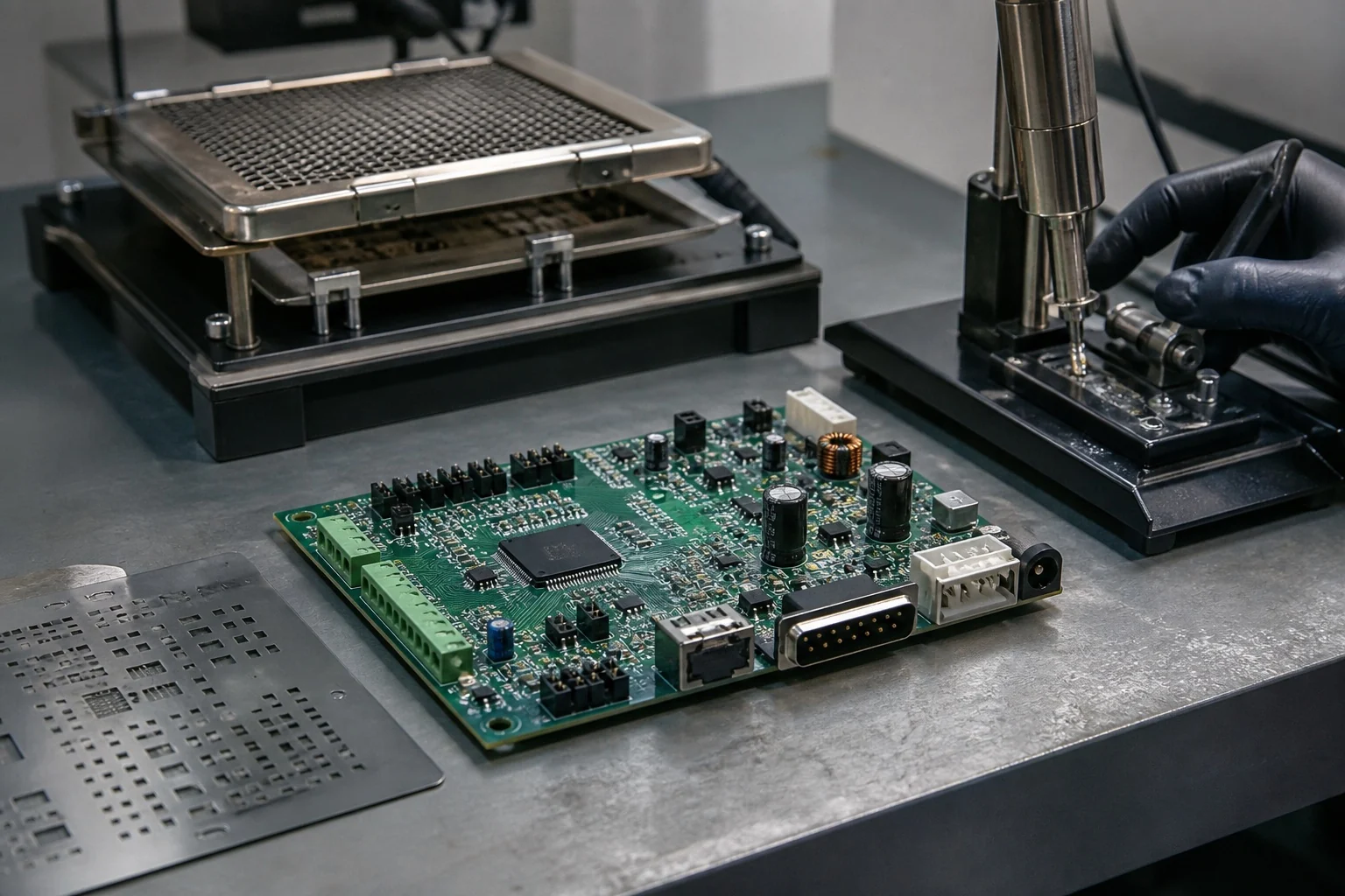
In short
SMT mounts parts on PCB surface pads; through-hole assembly inserts leads into plated holes before soldering. SMT helps with dense layouts and automated placement. Through-hole may suit connectors or heavier parts that need additional mechanical retention. Many designs use both. Choose from the component, product loads, quantity and assembly plan—not a universal cost or strength rule.
For practical steps on BOM, placement data and assembly drawings, see the PCB assembly guide.
What changes when you choose SMT or through-hole?
Surface-mount technology (SMT) places components on pads on the PCB surface. Solder paste, placement and reflow are a common route. Through-hole technology (THT) uses component leads inserted into plated holes, followed by a soldering process suited to the board. A PCB can contain both types.
The choice affects board area, available component packages, assembly sequence, tooling, access for soldering and inspection, and how the product handles physical loads. Start with the exact components and the enclosure or cable interfaces rather than choosing a process from a headline comparison.
Compare the design and production trade-offs
| Question | SMT | Through-hole |
|---|---|---|
| Where does the part sit? | On pads at the board surface; components may be placed on one or both sides when the design and process allow. | Leads pass through plated holes; the part body and solder-side access need space. |
| Which parts fit? | Useful for dense ICs and small passives available in surface-mount packages. | Useful where a selected connector, terminal, transformer or other leaded part needs this package and mounting route. |
| How is it soldered? | Often solder paste and reflow; the route depends on the package and board. | Wave, selective, pin-in-paste or controlled hand soldering may be used, depending on access and the component limits. |
| What about mechanical loads? | Surface pads can work well when loads are supported by the product design. | Leads provide a through-board anchor, but connectors and heavy parts may still need screws, brackets or other support. |
| How is it checked? | SPI and AOI can check selected visible process features; X-ray may be planned for hidden joints. | Visible joints can be inspected; hidden conditions or electrical behavior need methods chosen for the design. |
No row is a universal capability promise. Confirm the actual package, line, soldering access, inspection plan and acceptance criteria with the assembler.
When might through-hole be worth the extra space?
Through-hole is often considered for connectors that see repeated mating, larger terminals, heavy components or a part available only in a leaded package. It does not make a product automatically vibration-proof. Cable strain, board support, fasteners, enclosure tolerances and the component manufacturer’s guidance still matter.
High current alone does not force a through-hole choice. Evaluate the complete current path, component rating, copper, connector and thermal design. Likewise, a surface-mount connector can be appropriate when its specified retention and the product support match the loads.
What does the assembly cost comparison really depend on?
SMT may need stencil, placement-program and setup work. Through-hole may need insertion labor, wave or selective-solder tooling, masking and extra handling. Either route can carry testing, rework and material costs. There is no reliable “after a few dozen boards” crossover that applies to every design.
Ask for quotes against the same BOM, quantities and acceptance scope. Separate one-time tooling from recurring assembly cost, and include the price and availability of the actual components. If changing a package requires a board redesign or requalification, include that work in the decision.
Plan inspection for the joints you actually have
AOI evaluates visible features; it cannot see every connection. X-ray may help examine selected hidden joints, including some BGA connections, when the project specifies the method and acceptance criteria. Visual inspection of through-hole joints also has limits. Electrical and functional tests answer different questions and need their own coverage plan.
For a mixed board, identify which parts are SMT and which are through-hole in the BOM and assembly drawing. Confirm solder-side access, reflow exposure, board support and the order of operations before the first build. See the mixed-technology assembly service and the through-hole design checklist for practical preparation.
What to send for a manufacturing review
- Current Gerber or ODB++ data, drill files and stackup.
- BOM with exact manufacturer part numbers and fitted variants.
- Component placement data and assembly drawings showing orientation and soldering side.
- Quantity, target build stage, mechanical loads and required inspection or test.
These inputs let the assembler recommend a route and identify where the design needs support, tooling or a test decision. See SMT assembly and through-hole assembly for the individual services.
FAQ
Common questions
Is SMT always cheaper than through-hole?+
No. Cost depends on the component set, stencil or tooling needs, placement and insertion work, quantity, inspection and test. Compare project-specific quotes rather than using a fixed quantity threshold.
Can one PCB use SMT and through-hole parts?+
Yes. Many designs combine surface-mount circuitry with leaded connectors or other through-hole components. The soldering order and access need to be planned for the actual board.
What makes a small SMT package harder to assemble?+
Pad geometry, stencil aperture, solder-paste volume, placement accuracy, component packaging and inspection access all matter. Give the assembler the exact part number, land pattern, board layout and quantity so those constraints can be checked together; package size alone is not a reliable go/no-go rule.
Is through-hole always more reliable?+
No. Through-board leads can provide mechanical retention, but product reliability depends on loads, support, solder quality, materials and test conditions. Neither method is automatically better for every use.
Does through-hole always take longer?+
Not always. Lead count, insertion method, soldering route, tooling and batch size affect time. A mixed board may add process steps; ask for a schedule based on the actual BOM.
Which process should I use for a prototype?+
Build the prototype as close as practical to the intended product design. If the production package or process will change, plan to check the affected fit, assembly and performance again.
Technical references
Sources used for this guide
These sources explain the standards, materials or process details discussed above. Check the current revision when applying them to a new design.