
Wave soldering
Use a controlled wave route when the board has a suitable through-hole population and accessible solder side.
Through-hole PCB assembly is often needed for connectors, relays, transformers and larger leaded parts. PCBArise reviews hole fit, solder-side access and the rest of the component mix before choosing wave, selective or hand soldering.
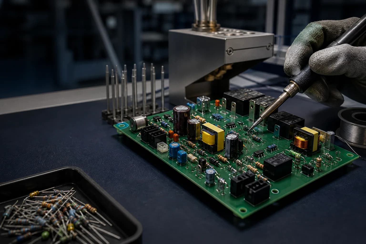
Through-hole PCB assembly installs component leads through plated or non-plated board holes before soldering. The process is often chosen for connectors, relays, transformers, large capacitors and parts that need mechanical retention, but the final route depends on lead geometry, thermal mass, solder access and the rest of the PCBA.
Through-hole assembly is not one soldering step. Component geometry, copper area, board thickness, solder access and downstream operations determine the practical route.
Use a controlled wave route when the board has a suitable through-hole population and accessible solder side.
Apply solder to defined joints when SMT, connectors or thermal-sensitive areas make a full wave route unsuitable.
Use documented hand operations for selected joints, repair, odd-form parts or areas that need operator access.
Review hole size, annular ring, lead forming, keepout and insertion force before the line is released.
These rows describe the information needed to select a THT route; exact soldering, fixture and acceptance limits remain project-specific.
Send the through-hole component drawings and assembly drawing so engineering can confirm hole, lead and solder-access fit.
| Component families | Connectors, relays, transformers, terminal blocks, large capacitors and odd-form parts by review |
|---|---|
| Board data | Gerber or ODB++, NC drill, fabrication drawing and plated/non-plated hole definition |
| Assembly data | BOM, CPL where applicable, assembly drawing, polarity, insertion direction and no-populate notes |
| Soldering routes | Wave, selective or controlled hand soldering selected by joint access and board population |
| Thermal review | Copper planes, heavy terminals and component temperature limits considered in the solder profile |
| Mechanical review | Lead forming, hole fit, component height, keepouts and enclosure access checked before setup |
| Inspection | Visual, AOI where visible, X-ray where hidden and electrical or functional testing where defined |
| Secondary operations | Programming, coating, cable work, box build or packaging added only when drawings and procedures are available |
A through-hole component can be electrically correct and still be difficult to assemble if the hole, lead form, keepout, solder side or mechanical clearance is undefined. The review connects the component drawing to the fabrication and assembly package.
The review turns a mixed list of leaded components into a controlled THT process route.
Use THT when mechanical retention, connector strength, high-mass components or serviceable leaded parts matter to the product.
Terminal blocks, relays, connectors and power components in PLC, gateway and motor-control assemblies.
Large components and current-carrying parts that need defined mechanical and thermal handling.
I/O, cable, shield and chassis interfaces where insertion or vibration loads affect the joint design.
Quality documents
The published ISO records name Zhongshan Wenquan Electronic Manufacturing Co., Ltd. and its Zhongshan PCBA facility. They do not certify every PCBArise facility, service or product.


These are management-system certificates, not product or batch COAs. No batch inspection reports or COAs are currently published here.
These THT answers help define the soldering route, component data and inspection evidence before quotation.
A through-hole PCB assembly service inserts leaded components through board holes and solders them using a wave, selective or controlled hand process selected from the component mix and board access.
Yes. Mixed builds can be evaluated. The SMT, through-hole and secondary-operation sequence is selected from component location, solder access, thermal exposure and inspection requirements.
Provide fabrication data, NC drill files, BOM, assembly drawing and component drawings where hole, lead form, polarity or mechanical fit is not unambiguous.
Inspection is matched to the joint and product risk. Visible joints can use visual or optical inspection, while hidden or electrically critical areas can require X-ray, ICT, flying probe or functional testing.
Compare through-hole with SMT, mixed-technology, testing and turnkey assembly before releasing the build package.
Share the fabrication data, BOM, component drawings, assembly drawing and required soldering or test evidence for a THT review.