
Commercial and industrial UAV flight-control, navigation, payload and telemetry boards
Industries / PCB & PCBA
Aerospace & UAV PCB Manufacturer
UAV and aerospace electronics pack sensing, control, communications and power into boards that must fit tight weight and space limits. PCBArise can review PCB fabrication and assembly for flight-control, payload, telemetry and eVTOL electronics. Share the operating environment, board design and test needs so the proposed build matches your product; any special data-handling or end-use requirements should be agreed before files are shared.
Aerospace ElectronicsUAV ElectronicsAvionics BoardsFlight-Control PCBA
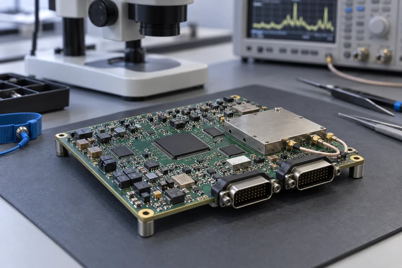
Product useDrone PCB Assembly and Avionics PCB ApplicationsChosen for your product
Board constructionUAV PCB Construction for Flight-Control Electronics
Assembly routeDrone PCB Assembly and Avionics PCB Applications
Quality checksUAV Quality, Configuration & Data Review
Typical applications
Drone PCB Assembly and Avionics PCB Applications
UAV buyers need a PCB partner around the actual product: flight-control, navigation, payload, telemetry, sensor, power or ground-support electronics. The application and end-use boundary are identified before quotation.
Drone and eVTOL power-management and control electronics
Airborne sensor, data-acquisition and condition-monitoring modules
UAV communication, imaging and payload-interface boards
Ground-control, test and maintenance electronics for UAV programs
Prototype and production electronics with project-specific qualification scope
Engineering choices
What matters in a UAV PCB build
The right board depends on the aircraft and its job. Weight, vibration, heat, connectors, signal paths and the customer’s test plan should guide the PCB construction and assembly choices.
Flight-control boards combine high-speed digital, RF, sensors and power conversion in a small volume
Weight, vibration, thermal cycling and power integrity constrain the board as one airborne product
UAV and eVTOL programs need configuration control, revision discipline and a clear prototype qualification path
Materials, workmanship, inspection and test evidence must match the customer’s quality system
Traceability and change history follow the approved product and acceptance plan
Data handling, end-use and acceptance requirements are reviewed before files are shared
Board and process options
UAV PCB Construction for Flight-Control Electronics
Rigid, multilayer, HDI, controlled-impedance and high-Tg constructions are considered against the UAV or eVTOL product’s weight, thermal, signal, mechanical and qualification requirements.
Product focus
Aerospace and UAV projects need a clear qualification boundary.
Flight profile, environmental exposure, configuration control, data handling and acceptance evidence are reviewed before a manufacturing route is released.
- Avionics, UAV flight-control and payload scope
- Configuration and traceability records
- Qualification and data-handling review
PCB options for UAV flight electronics
Compare board construction with weight, heat, vibration and signal needs
| Parameter | Specification |
|---|---|
| Layer Count | 1–40 Layers |
| Base Material | FR-4, High-Tg FR-4, halogen-free FR-4, Rogers, Taconic/AGC, PI, aluminum, PTFE/Teflon, F4B and other specialty laminates |
| Board Thickness | 0.10–10.0 mm |
| Copper Thickness | 0.5–12 oz, depending on board type and construction |
| Controlled Impedance | ±10% standard; ±5% for tighter requirements |
| Surface Finishes | HASL, Lead-Free HASL, OSP, ENIG, Immersion Silver, Immersion Tin, ENEPIG, Hard Gold, Gold Finger and selective finishes |
Board and process options
UAV RF, HDI & Rigid-Flex Options
Compact flight electronics may require HDI, fine-pitch fanout, rigid-flex, RF material or back drilling. These construction choices are confirmed against the released UAV stackup, airframe interface and qualification plan.
Product focus
Aerospace and UAV projects need a clear qualification boundary.
Flight profile, environmental exposure, configuration control, data handling and acceptance evidence are reviewed before a manufacturing route is released.
- Avionics, UAV flight-control and payload scope
- Configuration and traceability records
- Qualification and data-handling review
RF, HDI and rigid-flex board options
Choose the interconnect approach that fits the flight-control or payload design
| Parameter | Specification |
|---|---|
| Min Laser Microvia | 0.075 mm |
| HDI Structures | 1+N+1, 2+N+2, multi-step HDI and Any-Layer HDI |
| Via Technology | Blind vias, buried vias, stacked vias, staggered vias, via-in-pad, VIPPO / POFV, resin-filled and plated-over vias |
| Back Drilling | Supported |
| Warpage Control | ≤0.5% available when specified, subject to stack-up and design review |
| High-Speed / High-Frequency Materials | Rogers, Taconic/AGC, PTFE/Teflon, F4B, High-Tg FR-4 and other low-loss specialty laminates |
Assembly considerations
Materials for UAV & eVTOL Electronics
Material, finish, copper, coating and cleanliness decisions are reviewed against the customer’s approved list, thermal profile, signal requirements, airframe interface and acceptance documentation.
Options to discuss
Start with what your design needs.
We can confirm the workable combination after reviewing your files.
High-Tg TG170FR-4RogersTaconicPIRigid-FlexENIGENEPIGImmersion SilverOSPHard GoldConformal Coating
What to send
Choose for the product you are building.
- Avionics, UAV flight-control and payload scope
- Configuration and traceability records
- Qualification and data-handling review
Board and process options
Drone PCB Assembly for Flight-Control & Sensing
Fine-pitch processors, sensors, connectors, shields, power devices and mixed-technology content are assembled to the approved UAV flight-control BOM, drawings, workmanship class, inspection plan and test requirements.
Product focus
Aerospace and UAV projects need a clear qualification boundary.
Flight profile, environmental exposure, configuration control, data handling and acceptance evidence are reviewed before a manufacturing route is released.
- Avionics, UAV flight-control and payload scope
- Configuration and traceability records
- Qualification and data-handling review
UAV control and payload assembly options
Match package, connector and thermal needs to the assembly process
| Parameter | Specification |
|---|---|
| Min Component Size | 01005 (0.4 × 0.2 mm) |
| Min BGA Pitch | 0.25 mm |
| Placement Accuracy (X/Y) | ±0.025 mm (±25 μm) |
| Max PCB Assembly Size | 400 × 1200 mm(Min 50 × 50 mm; applicable process-line envelope, subject to board support and panelization review) |
| Warpage Control | ≤0.5%(Subject to board construction and assembly process review) |
| Reflow Atmosphere | Air / Nitrogen(Nitrogen reflow on applicable lines; oxygen target depends on the assembly route and profile) |
How the board fits the product
Aerospace and UAV projects need a clear qualification boundary.
Flight profile, environmental exposure, configuration control, data handling and acceptance evidence are reviewed before a manufacturing route is released.
- Avionics, UAV flight-control and payload scope
- Configuration and traceability records
- Qualification and data-handling review
Aerospace ElectronicsUAV ElectronicsAvionics BoardsFlight-Control PCBA
Inspection, testing and records
UAV Quality, Configuration & Data Review
PCBArise can review project-specific inspection, electrical test, functional test, traceability, configuration, NDA and data-handling requirements. The applicable customer and legal requirements must be confirmed before release.
ISO 9001:2015ISO 14001:2015Configuration ControlNDA ReviewProject Acceptance Records
Build files
Keep the board revision, BOM and assembly drawings together so the factory builds the intended configuration.
Inspection and test
Choose optical, X-ray, electrical or functional checks for the defects that matter to this product.
Material tracking
Agree which material and production records you need to retrieve after shipment.
Design changes
Decide who can approve a material, component or process change before it reaches the line.
Quality documents
Preview & download certificates
The published ISO records name Zhongshan Wenquan Electronic Manufacturing Co., Ltd. and its Zhongshan PCBA facility. They do not certify every PCBArise facility, service or product.


These are management-system certificates, not product or batch COAs. No batch inspection reports or COAs are currently published here.
Frequently asked questions
Common questions about this PCB application
Start with the board, environment and files you have; the detailed route depends on your design.
Can you provide UAV PCB assembly for drone and eVTOL projects?
Yes. We can review drone, UAV, eVTOL, flight-control, sensing, power and communication electronics. The application, end use, materials, qualification, traceability, data handling and acceptance requirements are confirmed before quotation.
How are UAV PCB quality requirements reviewed?
The review can cover the operating environment, materials, workmanship, inspection, electrical or functional test, traceability, configuration control and project acceptance records. The final evidence plan follows the released design and customer requirements.
Do you support drone flight-control and eVTOL electronics?
We can review flight-control, navigation, telemetry, payload, sensing, power-management and communication boards for UAV and eVTOL programs. Send the released design, operating environment, qualification plan and acceptance criteria for an engineering assessment.
How do you handle UAV traceability and configuration control?
The required record set is defined by the project and can include the approved BOM and revision, component lots, inspection and test records, change history and shipment release evidence. The customer’s configuration and quality requirements govern the final process.
Can you support high-vibration UAV electronics?
We can review board construction, component support, connector interfaces, mechanical constraints, thermal conditions and test requirements against the project’s vibration and operating profile.
What should I send for a UAV PCB quote?
Send the released Gerber or ODB++ files, BOM, drawings, stackup, material and finish requirements, environmental profile, qualification and test plan, workmanship class, traceability and configuration requirements, end-use information, and any NDA or data-handling instructions.
Related PCB pages
Explore the board and assembly options behind this product.
Use the related PCB, PCBA and quality pages to plan the next part of your build.
PCBArise resource
High Reliability PCB
Quality, inspection, traceability, and acceptance planning.
PCBArise resourceRigid-Flex PCB
Compact interconnects for UAV assemblies.
PCBArise resourceHigh Frequency PCB
RF materials and controlled-impedance construction.
PCBArise resourcePCB Assembly Capabilities
Fine-pitch, mixed-technology, inspection, and test.
PCBArise resourceCertifications & Compliance
Applicable quality systems and project documentation review.
Define the aerospace and UAV PCB build scope.
Send the released design data, environmental profile, qualification plan and end-use requirements for a project-specific review.