
Aluminum core
A cost-effective insulated metal substrate for LED, power conversion and general thermal management.
Metal core PCB manufacturing uses an aluminum or copper-backed thermal path to move heat away from power and lighting components through a controlled dielectric system. Aluminum PCB is commonly evaluated for LED lighting, power conversion, motor control and other assemblies where heat must move into a chassis or heatsink.
An IMS board only improves thermal performance when the component interface, dielectric, metal base and final heatsink connection work as one path.
A cost-effective insulated metal substrate for LED, power conversion and general thermal management.
Greater thermal spreading and mechanical mass where the application justifies added material cost and weight.
Copper circuitry over thermally conductive dielectric and a metal base—the shortest standard thermal path.
Additional routing and reference layers combined with a metal-backed structure after stackup-level review.
Thermal conductivity is one property, not the full result. Dielectric thickness, copper area, interface quality and the external heatsink determine the assembled thermal path.
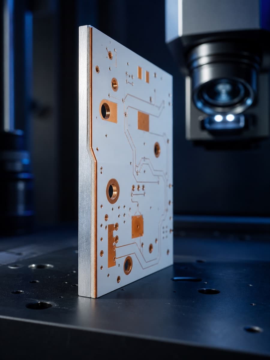
Insulated metal substrate construction reference
| Circuit layer count | 1–4 typical; advanced structures by review |
|---|---|
| Metal base | Aluminum or copper |
| Thermal dielectric | Ceramic-filled electrically insulating layer |
| Thermal conductivity | Up to 3.0 W/m·K for qualified aluminum materials |
| Copper weight | 1–4 oz typical; heavier copper by evaluation |
| Finished thickness | Defined from copper, dielectric and metal-base stack |
| Surface finish | ENIG, OSP or lead-free HASL as the assembly requires |
| Profile processing | Routing, scoring and mechanical features by drawing |
| Testing | Electrical test plus dimensional and visual inspection as specified |
Capability values are design-dependent. Material, copper weight, layer count, via structure, finished thickness and surface finish can change the achievable combination.
A thinner or more conductive dielectric can reduce thermal resistance, but electrical withstand, copper geometry and process robustness still govern the acceptable construction.
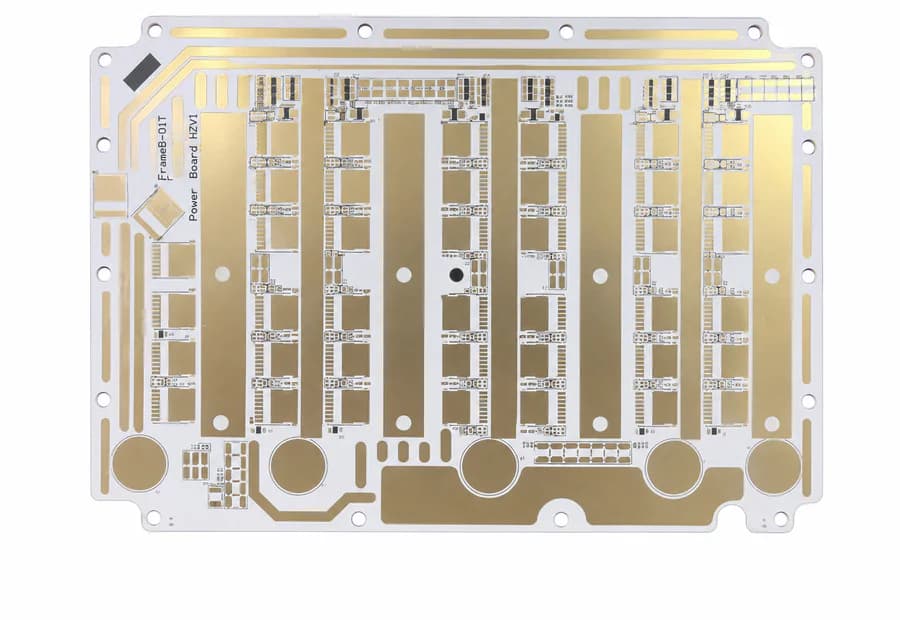
Review dielectric thickness, thermal conductivity, copper spreading, isolation and the external heatsink interface together.
Use these examples as a starting point. The board construction still follows the product’s electrical, mechanical and qualification requirements.
High-brightness lighting modules that must move heat away from LED junctions.
Power supplies, inverters and converter stages with concentrated thermal loads.
Headlamp, signal and interior-lighting modules with temperature and reliability constraints.
Power-device mounting and control assemblies requiring a compact heat path.
Controls and power electronics installed against a chassis or heat spreader.
Power modules where electrical isolation and thermal transfer must be designed together.
Quality documents
The published ISO records name Zhongshan Wenquan Electronic Manufacturing Co., Ltd. and its Zhongshan PCBA facility. They do not certify every PCBArise facility, service or product.


These are management-system certificates, not product or batch COAs. No batch inspection reports or COAs are currently published here.
These answers clarify the material, thermal and fabrication decisions behind a metal core PCB build.
A metal core PCB uses a metal base—commonly aluminum or copper—under an electrically insulating, thermally conductive dielectric and the copper circuit. It is designed to move heat into the mechanical assembly more directly than standard FR-4.
A metal core PCB is the broader construction family: it uses a metal base, commonly aluminum or copper, under an electrically insulating, thermally conductive dielectric. An aluminum PCB is the common aluminum-base option; copper core is selected when greater heat spreading or thermal mass justifies additional cost and weight.
Qualified aluminum material systems are available up to 3.0 W/m·K. Final thermal performance also depends on dielectric thickness, copper coverage, interfaces and the external heatsink.
Yes, multilayer insulated-metal constructions can be evaluated. They require a stackup-specific review because routing layers, isolation, lamination and the metal-backed thermal path interact.
Compare metal core with heavy copper, rigid FR-4, capability limits and DFM review before selecting a thermal route.
Share the available Gerber, ODB++, drawing, stackup or project requirements with the PCBArise team.