

In short
Define the defect, allowed disposition, exact procedure and post-work acceptance before touching the board. Rework returns a nonconforming assembly to its original requirements; repair restores function or usability through an authorized method that may differ from the original design. Accept the result only after inspecting components, joints, pads, traces, holes, mask, cleanliness and heat effects, then repeating the affected electrical, programming or functional tests.
- Keep touch-up, rework, repair and post-rework inspection distinct because they change different things and need different authorization.
- Route by observed damage and product requirement—not by a universal rework-count or temperature rule.
- Define acceptance for the component, interconnect and base board, including pads, traces, plated holes, solder mask, cleanliness and adjacent heat effects.
- A complete record identifies the defect, unit, material, tool/program, qualified person, heat history, inspection, retest and final disposition.
Write the disposition route and acceptance result before rework begins. Identify the defect, affected unit and original requirement; decide whether the action is touch-up, rework, repair, use-as-is or scrap; then cite the authorized procedure, materials, tools, qualified person and post-work checks. Accept the board only when the component, solder joint, pad, trace, hole, mask, cleanliness, adjacent area and affected functions meet the documented result.
What is the difference between rework, repair, touch-up and post-rework inspection?
Rework returns the assembly to its original requirements; repair uses an authorized method to restore an acceptable result when the original physical configuration cannot simply be recreated. Touch-up is a limited operation on an existing connection or surface, such as correcting a local solder condition without removing the component. Post-rework inspection is the independent decision step that checks the work and affected area; it is not another name for the operation.
| Term | What changes | Required definition | Example decision |
|---|---|---|---|
| Touch-up | A local existing joint or finish is corrected without a broader remove-and-replace route. | Allowed local action, material, workmanship result and inspection. | Correct an insufficient local solder condition, then inspect the joint and adjacent mask. |
| Rework | Nonconforming assembly is returned to the original drawing/specification result. | Removal/replacement method, original acceptance source and affected retest. | Remove a wrong component and install the released part at the same design location. |
| Repair | Damaged feature is restored by an authorized method that may differ physically from the original. | Engineering disposition, repair drawing/procedure and product-specific acceptance. | Restore a damaged conductor with an approved repair feature and verify electrical/mechanical integrity. |
| Post-work inspection | No intended product change; it judges the result and collateral area. | Inspection method, acceptance criteria, tester independence when required and records. | Inspect joint, land, trace, mask, residue and nearby parts before retest. |
IPC-7711/7721 provides procedure guidance for rework, repair and modification. The finished assembly still needs the acceptance document, product drawing, contract class and stated exceptions that apply to that build. Do not invent a clause from memory or treat a procedure number as the complete acceptance criterion.
Which defects may follow a defined rework route, and which need engineering disposition or scrap review?
Use a predefined route only when the defect, assembly condition, procedure and post-work result all fall inside its stated limits. Wrong or misoriented parts, accessible solder anomalies and some damaged local finishes may be routable when pads, laminate and adjacent components remain suitable. Lifted or missing lands, damaged traces or plated holes, delamination, charring, underfill/coating complications, unknown prior heat history or safety-critical impact need engineering evaluation. Scrap review is appropriate when integrity cannot be demonstrated or the authorized repair would not meet product requirements.
| Observed condition | Possible route | Minimum decision inputs | Do not proceed when |
|---|---|---|---|
| Wrong, missing or reversed component; site undamaged | Defined component remove/replace rework | Correct MPN, package guidance, moisture state, access, removal/install procedure, inspection and retest | Pad, trace, laminate or nearby part condition is uncertain. |
| Local solder anomaly on an accessible termination | Defined touch-up or rework route | Applicable joint acceptance, alloy/flux compatibility, tip/nozzle and inspection method | The operation can disturb hidden joints, coating, sensitive parts or required geometry. |
| Lifted/missing pad or damaged conductor | Engineering-authorized repair or scrap review | Electrical function, current/signal demand, mechanical anchoring, geometry, coating and test | Inner-layer connection, remaining laminate or service environment cannot be verified. |
| Damaged plated through hole | Engineering-authorized repair or scrap review | Layer connectivity, barrel/land condition, lead fit, structural need and inspection access | Required internal connection or mechanical strength cannot be restored and inspected. |
| Delamination, blister, charring or widespread heat damage | Engineering/material review, commonly scrap assessment | Extent, affected layers, insulation, moisture/contamination and product criticality | Damage boundary or electrical/mechanical integrity is indeterminate. |
| Unknown history or repeated prior work | Hold for history and condition review | Unit trace, previous operations, heat exposure, component/board limits and current inspection | A universal rework-count guess is the only justification. |
How should components, pads, traces, holes and solder mask be accepted after rework?
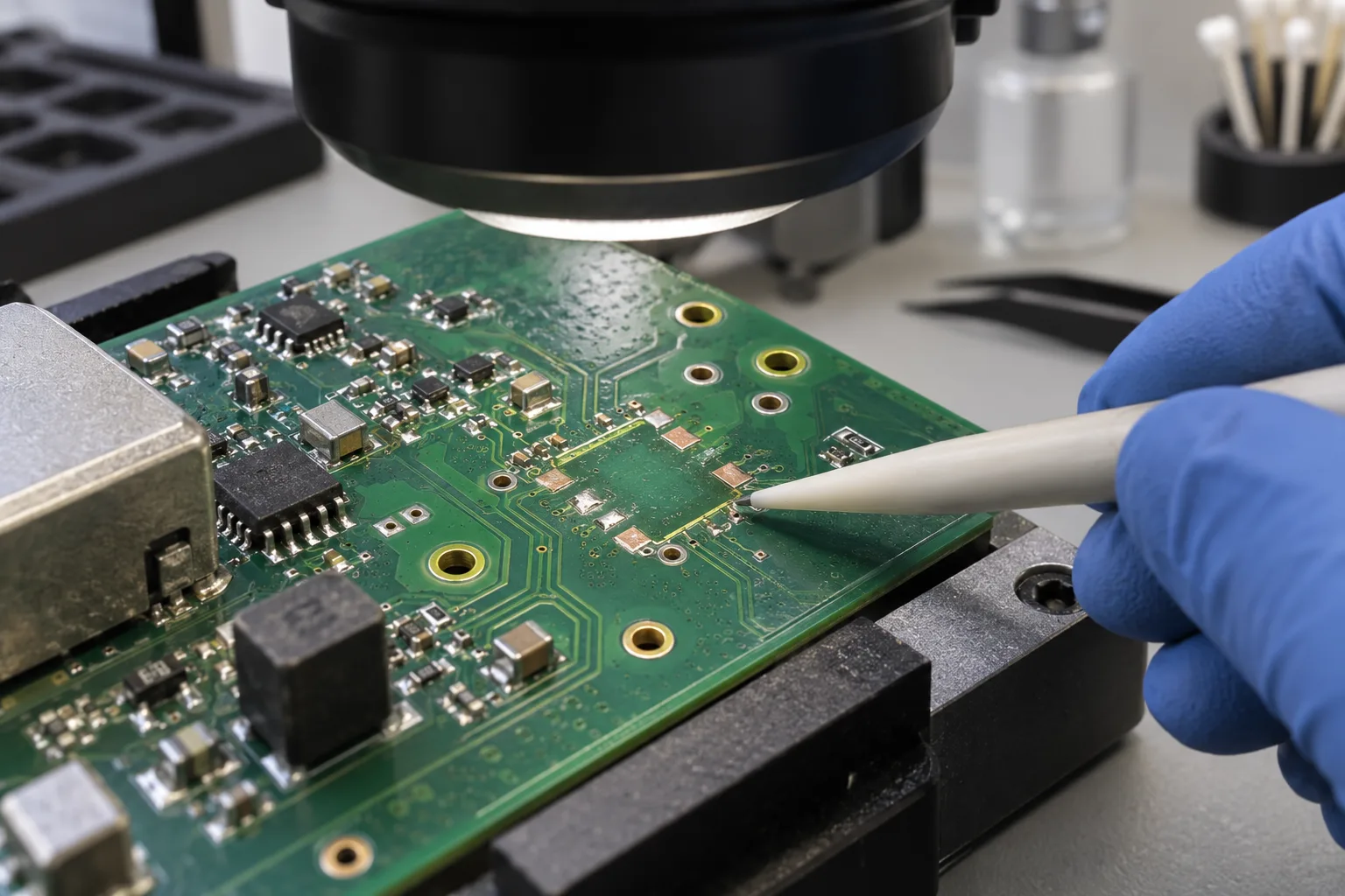
Define a separate observable result for each affected feature. The replacement component must have the correct identity, orientation, seating and condition. Its terminations must meet the applicable assembly-acceptance criteria. Lands and traces must remain attached and continuous, with no unapproved reduction, lift or exposed damage. Plated holes need the required electrical layer connection, acceptable barrel/land condition and mechanical function. Restored solder mask must cover and insulate the intended area without contaminating a solderable surface.
| Feature | Acceptance result to define | Useful inspection/test | Record |
|---|---|---|---|
| Component | Correct approved part; no handling, package or lead damage; correct orientation and seating | Marking/part trace, magnified visual, package-specific inspection | Installed MPN/lot when required and affected reference designators |
| Solder connection | Meets cited product/workmanship criteria; no shorts, opens or disturbed neighboring joints | Visual/magnified inspection plus X-ray or electrical check only where suitable | Criteria/revision, method, result and anomaly image reference |
| Land and trace | Attached, continuous, undamaged beyond the approved repair geometry | Magnification, continuity/resistance where meaningful, dimensional or adhesion check if specified | Location, observed condition and repair drawing/procedure when used |
| Plated through hole | Required layer connection, barrel/land condition, lead fit and mechanical support restored | Visual access, electrical continuity and any defined structural inspection | Hole/reference ID, layers or nets affected, result |
| Solder mask / coating | Required insulation and coverage restored; pads, test points and keepouts remain usable | Magnified visual and cure/coverage check from the approved material process | Material, batch/expiry when required, cure route and inspected area |
How are cleanliness and heat effects accepted after rework?
Specify the approved flux and cleaning combination, the areas to inspect and the product-level cleanliness requirement before the work. “Clean after rework” is insufficient because residues can remain under low-clearance parts, shields, coatings or around repair materials, while an incompatible solvent or aggressive brush can cause new damage. Record the material and cleaning route; inspect for visible residue, fibers, disturbed coating and trapped contamination, then apply any required quantitative cleanliness test defined by the product plan.
Heat acceptance starts with a package- and board-specific procedure, not a universal temperature or cycle count. Define the heating method, measured location, profile or operating window, moisture preparation, adjacent-component protection and abort conditions from the component, PCB, material and product requirements. Record actual exposure when the procedure requires it and inspect for discoloration, delamination, pad lift, mask damage, component deformation and disturbed neighboring joints.
What must the rework instruction define before a technician starts?
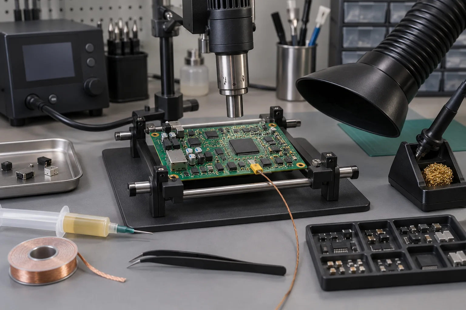
Define the unit, defect, route, materials, tools, program, skill, thermal controls and post-work checks in one executable instruction. Include ESD and handling needs; coating or adhesive removal and restoration; replacement-part identity and moisture status; alloy, flux, solder form and cleaning material; tip, nozzle, fixture and board support; heating sequence and measurement points; component-removal and site-preparation method; inspection; electrical/programming/functional retest; and stop conditions.
Personnel qualification must match the operation and the organization’s invoked workmanship system. A training certificate alone does not make every pad, BGA, plated-hole or conductor repair authorized. The instruction should name the skill or certification required and who may make the final disposition.
What post-rework inspection and testing are required?
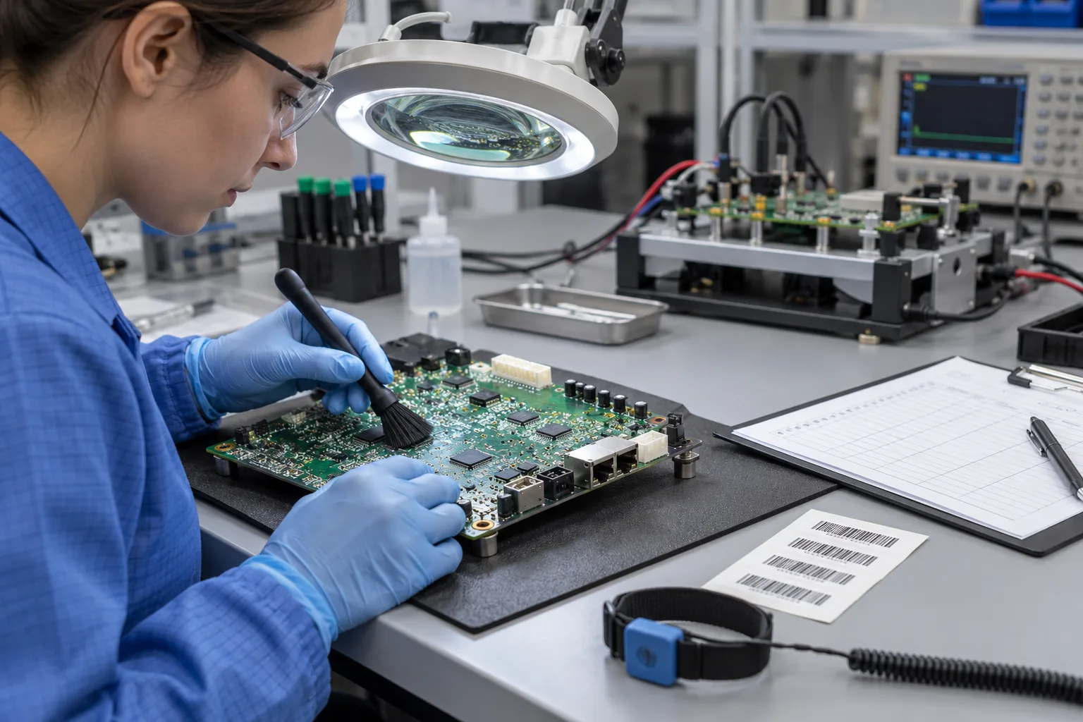
Repeat every inspection and test whose evidence the operation could invalidate, then add checks for collateral damage. Component replacement normally needs identity/orientation and solder-joint inspection, plus continuity, programming or functional tests tied to the affected nets and behavior. Work near hidden terminations may need a suitable indirect inspection. Conductor or hole repair needs the defined electrical check and any mechanical, insulation or environmental evidence required by the product.
What can a copyable PCBA rework record look like?
Use one record that follows the unit from defect discovery through final disposition. Keep actual values and references where the process generates them; never reduce the history to “reworked—pass.”
Identification: Project/product [ ] | PCBA part/rev [ ] | Unit/serial/panel [ ] | Date/station [ ].
Condition: Defect code and description [ ] | Reference designator/location/net [ ] | Discovery stage [ ] | Original requirement [ ] | Photos/evidence [ ] | Prior work/heat history [ ].
Disposition: [touch-up / rework / repair / use-as-is / scrap review] | Procedure/drawing and revision [ ] | Authorization [ ] | Reason [ ].
Execution: Removed part/lot [ ] | Installed part/lot [ ] | Solder/flux/cleaner/repair material and batch [ ] | Tool/nozzle/tip/fixture/program ID [ ] | Thermal profile or recorded exposure reference [ ] | Operator/qualification [ ] | Start/finish [ ] | Exceptions [ ].
Acceptance: Component/orientation [ ] | Solder joints [ ] | Pads/traces/holes [ ] | Mask/coating [ ] | Cleanliness [ ] | Adjacent area/heat effects [ ] | Electrical/programming/functional retest and actual result [ ] | Inspector/date [ ] | Final disposition [ ].
Why should buyers define rework acceptance before the pilot build?
It prevents schedule pressure from turning a technical disposition into an undocumented judgment. Before the pilot, identify defects with standard routes, conditions requiring engineering review, customer-notification triggers, traceability fields and tests that must be repeated. That lets manufacturing respond consistently while keeping damaged-base-board repairs, unknown history and safety-impacting conditions visible.
Use the assembly traceability guide to connect the record to units and material lots, and the component-alternate guide when the proposed replacement is not already released. The next practical step is to attach the completed matrix and record template to the project’s inspection and test plan.
About the author
PCBArise Electronics
PCBArise Electronics publishes this guide to help design and NPI teams prepare clearer manufacturing files. The requirements for any actual build are confirmed from its current design package.
FAQ
Common questions
What is the difference between PCBA rework and repair?+
Rework returns a nonconforming assembly to its original drawing or specification result, such as replacing a wrong component with the released part. Repair uses an authorized method to restore an acceptable result after damage and may differ physically from the original design.
Is touch-up the same as rework?+
No. Touch-up is a limited correction to an existing connection or finish without the broader remove-and-replace operation normally meant by rework. Define its allowed action, material, workmanship result and post-touch-up inspection instead of using the terms interchangeably.
How many times can a PCBA be reworked?+
No universal number is valid for every assembly. Decide from the component, laminate, pad and coating limits, the actual thermal and mechanical history, the defect and repair route, product criticality and the ability to inspect and retest the result. Record each operation rather than relying on a guessed count.
What should be inspected after PCBA rework?+
Inspect the replacement component and orientation, solder connections, pads, traces, plated holes, solder mask or coating, cleanliness, nearby components and signs of heat or handling damage. Then repeat every electrical, programming or functional test whose evidence the work could invalidate.
When should a damaged PCBA go to engineering or scrap review?+
Escalate lifted or missing lands, damaged conductors or plated holes, delamination, charring, hidden or inner-layer uncertainty, underfill/coating complications, unknown prior work, safety impact or any condition outside the approved route. Scrap review is appropriate when required integrity cannot be restored and verified.
What belongs in a PCBA rework record?+
Include unit identity, original defect and requirement, disposition and authorization, affected location, removed and installed parts, materials, tools or program, qualified person, thermal history, procedure revision, inspection results, repeated tests, exceptions and final disposition.
Technical references
Sources used for this guide
These sources explain the standards, materials or process details discussed above. Check the current revision when applying them to a new design.
- Global Electronics Association — IPC-7711/7721D scope for rework, repair and modification
- NASA GSFC-STD-6001A — workmanship, process review and rework-cycle boundary context
- Infineon — package-specific rework, moisture, tooling and thermal-profile guidance
- ZVEI — rework process, cleaning and qualification guidance
- Circuit Technology Center — illustrated board and assembly rework/repair procedures
- Circuit Technology Center — localized cleaning procedure and limitations
- PCBSync — current IPC-7711/7721 terminology and acceptance-standard boundary
- Global Electronics Association — 2026 standards work on assembly, cleaning, inspection and traceability