
In short
A rigid-flex bend zone is a mechanical feature, not leftover routing space. Mark its start and end, bend line, inside radius, angle, static or dynamic use, flex thickness, expected cycles, and clearance or fixture constraints. Route copper for that motion, keep vias and components out unless deliberately designed otherwise, and show where coverlay and stiffeners begin and end. The fabricator needs the construction; the assembler needs the folded shape and support plan.
- Classify every bend as static (formed then held) or dynamic (repeated in service) before choosing a radius or flex construction.
- Dimension the bend zone, radius, angle, flex thickness, motion direction and keep-outs on the mechanical drawing; a rigid-flex Gerber alone does not carry this intent.
- Use trace routing, coverlay, copper type and layer arrangement that suit the stated bend; avoid casual vias, pads and stiffener edges in the flexing area.
- Give assembly the final folded envelope, fixture/support needs and the sequence in which the board may be bent and populated.
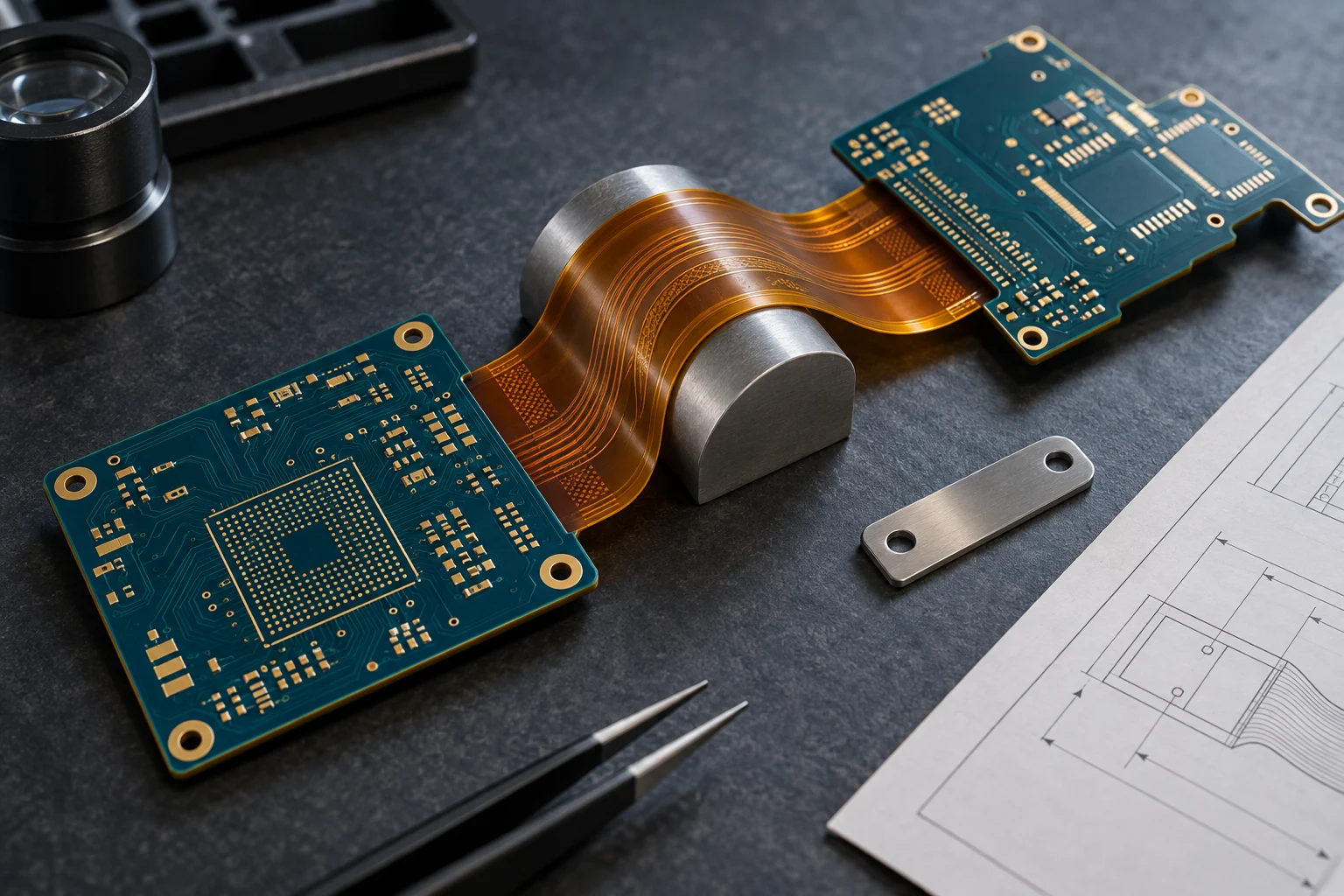
A rigid-flex bend zone should be drawn as a defined mechanical interface: where it starts, how far it bends, around what inside radius, how often it moves and what can enter the zone. A rigid section holds components and mounting features; the flex section carries the interconnect through a three-dimensional package. If the drawing says only “rigid-flex,” the fabricator cannot tell whether the flex is folded once during installation or must survive repeated motion, and the assembler cannot tell how the finished board is meant to be supported.
What must a rigid-flex bend zone define?
Define the motion before choosing the geometry. Mark whether the flex is static—formed during assembly or installation and then held—or dynamic, meaning it bends repeatedly during normal use. Then identify the bend line or bend area, inside radius, angle, direction of motion, available envelope, flex-section thickness, expected use cycles when dynamic, and any part, via, connector or fastener keep-out. This turns “make it fold here” into an instruction a fabricator, mechanical designer and assembler can all review.
The radius is a multiple of the finished flex-section thickness, not the total rigid-board thickness and not a number copied from an unrelated product. Published rules of thumb vary with flex layer count, copper construction and use case. Altium’s rigid-flex guidance, for example, distinguishes static ratios by construction and calls for a much more conservative dynamic bend range. Use such figures as a preliminary design screen; release the actual radius and construction for the selected product rather than presenting one multiplier as universal.
| Design question | Static flex-to-install | Dynamic flex in service |
|---|---|---|
| Motion definition | State installation fold, final angle and held position. | State bend angle, direction, cycle target, speed or duty pattern and lifetime environment. |
| Radius decision | Size from finished flex thickness and final packaging envelope, with an installation margin. | Use a larger, construction-specific radius and validate it against the required motion life. |
| Copper and routing | Keep routing smooth and avoid unnecessary discontinuities through the bend. | Prioritize ductile copper construction, layer arrangement and trace routing for cyclic strain. |
| Mechanical detail | Show how the flex is held after formation and where assembly may support it. | Show guides, moving interfaces, abrasion protection, strain relief and the permitted travel. |
| Acceptance | Verify final folded fit, clearances and electrical function for the released revision. | Define bend-cycle, electrical and mechanical evaluation appropriate to the product risk. |
How do you choose a bend radius without using a fake universal rule?
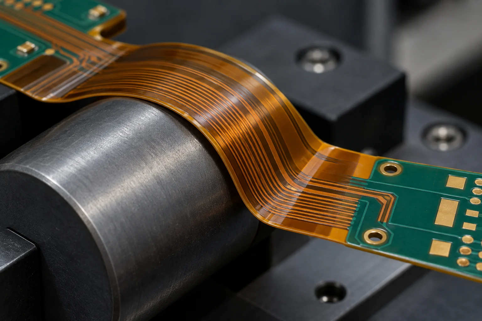
Start with finished flex thickness, construction and motion, then document the required inside radius. A one-layer flex tail, a double-sided flex circuit and a multilayer rigid-flex transition do not strain copper in the same way. More copper layers, thicker copper, adhesive layers, coverlay and a smaller radius generally increase stiffness or strain. Dynamic motion adds fatigue, so the required radius and construction must be tied to the movement the product will actually see.
Use the mechanical model to make the radius real. Check whether the enclosure, hinges, guides, mounting screws, connectors and nearby parts leave that inside radius after tolerances are applied. If the board must fold around a feature, show the feature and the permitted contact surfaces. If a bend is only made once during final assembly, say so; that allows the team to avoid paying or designing for a dynamic-life requirement it does not need.
A clear note might read: “Flex zone F1: static installation bend, 90° nominal, inside radius R = [value] mm, finished flex thickness T = [value] mm, bend direction shown. No vias, plated holes, components, stiffener ends or adhesive discontinuities in the marked bend zone. Final folded envelope and support fixture are shown on sheet [reference].” For dynamic motion, replace “static installation” with the bend angle, repeated-use condition and required cycle or validation requirement. The values belong to the product, not to this example.
How should copper, coverlay and layer arrangement pass through the bend?
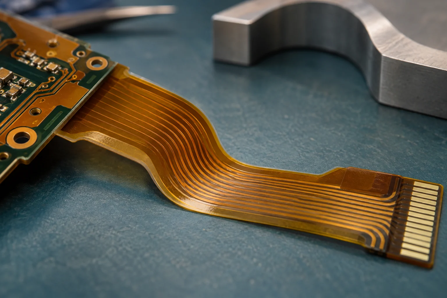
Route conductors to minimise strain in the direction of motion, then keep the stackup as flexible and balanced as the electrical job allows. In a simple bend, traces are commonly routed perpendicular to the bend axis so they follow the curve rather than concentrating stress at a sharp corner. Smooth transitions and sensible spacing reduce local stress concentration. On multi-layer flex, staggered routing can avoid stacking copper directly over copper in a way that creates an I-beam-like stiff region. The exact route remains a stackup decision, not a decorative layout rule.
Coverlay protects the flex circuit but it also contributes to the mechanical construction. Identify the coverlay type, openings, adhesive system and any local reinforcement in the stackup or drawing. Do not place a coverlay edge, a rigid transition, an abrupt copper change and a stiffener edge at the same stress line without deliberately reviewing the combined stiffness change. For cyclic motion, the copper form and flex stackup are central reliability inputs; a static design may tolerate a different construction but still needs a documented bend and handling plan.
Keep vias, plated through holes, component lands, heavy pads and sharp route corners outside the marked bend zone unless their presence is an intentional, qualified design feature. Altium’s rigid-flex documentation similarly warns against through holes in a bend, especially where motion is dynamic. The practical reason is simple: those features interrupt a flexing copper and dielectric system with a local stiff structure.
Where do stiffeners and rigid transitions belong?
Use a stiffener to support a connector, component or handling feature—not as an accidental ending at the bend’s highest-strain point. A polyimide, FR-4 or metal stiffener can make a connector tongue insertable, hold a component area flat, or support assembly. It changes local thickness and stiffness, so its start and end, adhesive overlap and relation to the bend line must be shown on the mechanical drawing.
Place the stiffener clear of the active bend zone unless the design specifically accounts for its effect. Likewise, define the rigid-to-flex transition and the flex tail length outside the rigid area. The fabricator needs to know which layers continue into flex, where coverlay replaces rigid solder mask, and how the rigid and flex stackups meet. The assembler needs to know when it is safe to bend the board, which side is inside the bend, and whether a fixture holds the final shape during soldering, test or installation.
What does the assembler need that Gerber data does not show?
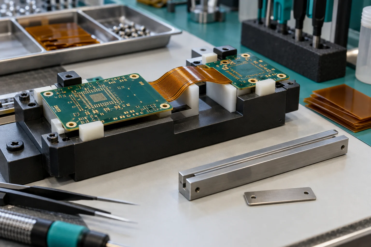
The assembler needs the final folded product, not only a flat circuit outline. Supply a controlled mechanical drawing or model that shows each flex zone, bend sense, final angle, radius, keep-outs, component clearance, connector insertion direction and any support fixture. State whether the board is bent before or after components are fitted, whether it must be held while soldering, and whether a protective film, tape, strain relief or chassis interface is installed later.
Give the same revision to the fabricator and assembler. If a mechanical change moves a stiffener, shortens a flex tail or tightens an enclosure radius, it can change the flex construction and assembly plan even if the electrical netlist did not change. Pair the mechanical drawing with the stackup, Gerber or ODB++ data, placement file, assembly drawing, BOM and product-level clearance requirements. That shared package prevents a correctly fabricated flex from being bent or supported in the wrong way on the line.
Five rigid-flex bend-zone mistakes to avoid
- Calling all bends “flex”: static installation and repeated dynamic motion create different radius, material and validation needs.
- Dimensioning only the flat outline: the board still needs a bend line, inside radius, angle, direction and three-dimensional clearance envelope.
- Routing a dense rigid-board pattern through the bend: vias, pads, sharp corners and stacked copper can turn a flex zone into a local stiffness problem.
- Letting a stiffener end on the bend line: identify its edge and move the stiffness transition out of the active bend unless the construction is designed for it.
- Giving assembly no folded model: a fabricator can make the flat circuit correctly while an assembler still lacks the sequence and support needed to form it safely.
Read the rigid-flex PCB and flexible PCB pages for service context. For a buildable product, provide the released stackup, bend-zone drawing and final folded envelope together; they are the information that lets a fabricator and assembler evaluate the real construction.
About the author
PCBArise Electronics
PCBArise Electronics publishes this guide to help design and NPI teams prepare clearer manufacturing files. The requirements for any actual build are confirmed from its current design package.
FAQ
Common questions
What bend radius should I use for a rigid-flex PCB?+
Set the inside radius from the finished flex thickness, copper and layer construction, and whether the bend is static or repeatedly dynamic. A static flex-to-install board and a moving hinge are not governed by the same ratio. Put the actual radius, angle and use condition on the mechanical drawing.
What is the difference between a static and dynamic rigid-flex bend?+
A static bend is formed during installation or assembly and then held in its final position. A dynamic bend moves repeatedly during product use. Dynamic motion introduces fatigue, so it needs a construction, radius, routing and validation plan designed for the expected movement rather than a one-time fold rule.
Can vias or components be placed in a rigid-flex bend zone?+
Avoid them in the active bend zone unless the construction deliberately supports them. Vias, plated holes, component pads and heavy features create local stiffness in a region meant to flex. Mark a keep-out on the mechanical drawing and keep the rigid-to-flex transition, stiffener edges and bend line separate where possible.
How should traces run through a rigid-flex bend?+
Route them for the stated bend direction with smooth geometry and without sharp local stress points. In a simple bend, traces commonly cross the bend axis rather than running along it; multilayer flex may need staggered routing. Confirm the route together with copper type, coverlay and the selected flex stackup.
What files should go with a rigid-flex PCB quote?+
Send the fabrication data, rigid and flex stackups, mechanical drawing or model with bend zones and final folded envelope, bend radius and angle, static or dynamic use, component placement, assembly drawing, BOM, stiffener or coverlay details, and any fixture or validation requirement. The electrical files alone do not define the mechanical product.
Technical references
Sources used for this guide
These sources explain the standards, materials or process details discussed above. Check the current revision when applying them to a new design.
- IPC design standards — flexible and rigid-flex PCB design references
- IPC PCB design for flex and rigid-flex course outline
- Altium documentation — rigid-flex routing, bend ratios and drawing requirements
- Altium — mechanical constraints, stackups and static versus dynamic bending
- Elephantech — September 2026 PCB manufacturing news index, checked for industry context