
In short
A PCBA first-article inspection should prove that one identified assembly matches the released PCB, BOM, placement, drawing, firmware and test package before the pilot lot continues. Check configuration first, then mechanical fit, polarity, workmanship and defined functions. Record every deviation, substitute, rework and open issue. A pass releases only the stated build configuration and checks; it does not prove every unit or every product requirement.
- Separate first-article inspection from bare-board first-piece checks, in-process patrols and final shipment inspection because each catches a different failure.
- Freeze one revision baseline for PCB data, BOM, CPL, assembly drawing, firmware and test instructions before judging the assembled board.
- Write checks as characteristic, source requirement, method, result, status and evidence instead of using a single “looks good” box.
- Carry deviations, alternates, rework and open actions into the release decision; a first-article pass is never a universal quality conclusion.
For repeatable pilot and small-batch orders, review the files, sourcing and schedule on the low-volume PCB assembly page.
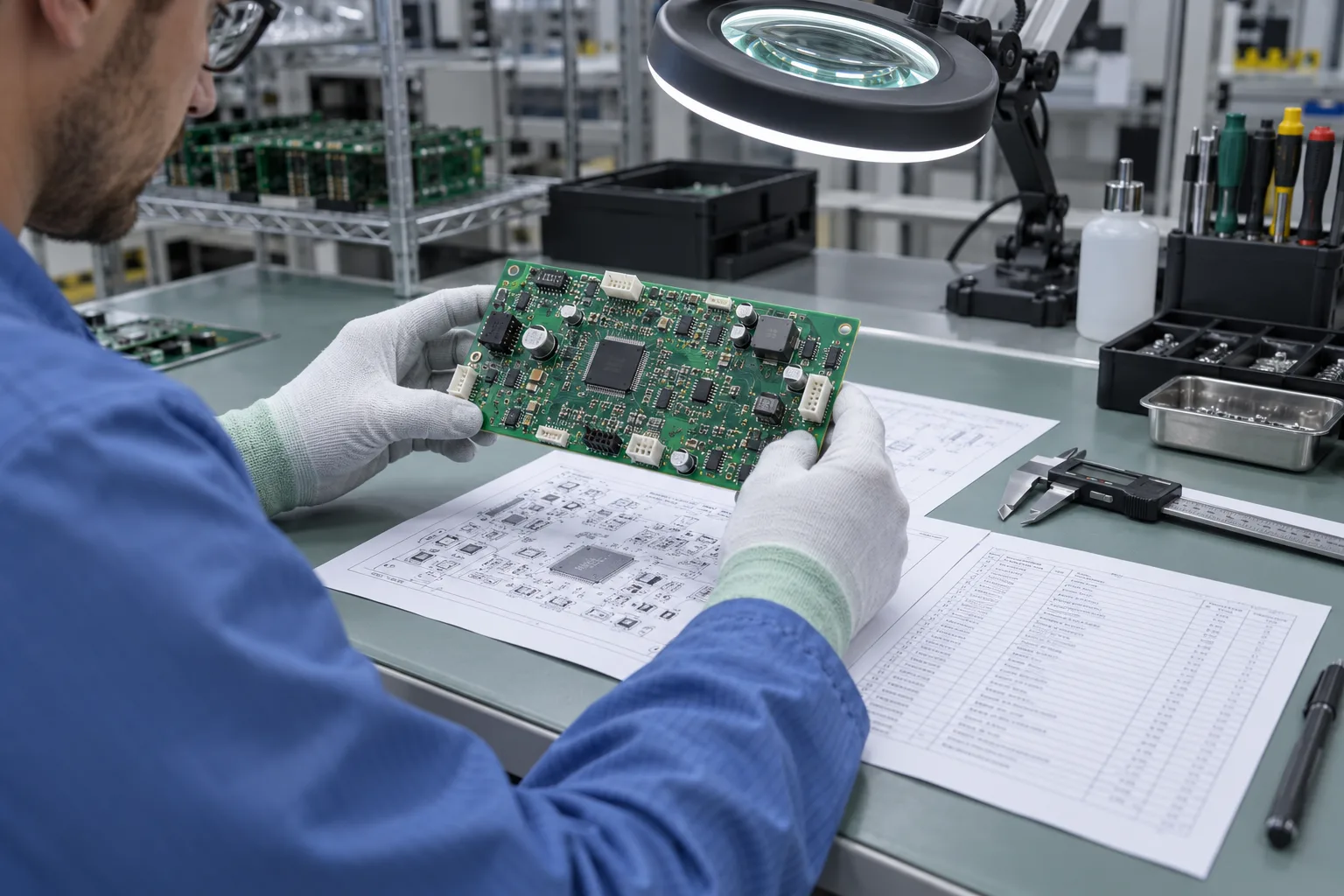
Inspect the first identified PCBA against one released product-and-process baseline before the rest of the pilot lot continues. Confirm PCB, BOM, CPL, assembly drawing, approved alternates, firmware and test instruction revisions first. Then verify mechanical features, component identity and orientation, soldering, programmed version and defined functions. Record actual results, deviations, rework and open issues; “FAI passed” alone is not an actionable record.
What does PCBA first-article inspection solve—and what does it not solve?
It catches repeatable setup and interpretation errors early; it does not prove long-term process capability, reliability or that every later unit conforms. A first article can reveal an outdated BOM, wrong reel, rotated part, mismatched placement file, connector-height conflict, incorrect firmware or unusable test instruction before those errors are copied across the pilot lot. Its conclusion applies only to the identified configuration, route and checks recorded.
| Check | Primary object | Question it answers | What it cannot replace |
|---|---|---|---|
| Bare-board first piece | Fabricated PCB before assembly | Does the board match the fabrication data, drawing and agreed bare-board checks? | Component placement, soldering, firmware or PCBA function. |
| First assembly / first article | First identified PCBA built from the intended setup | Do released data, materials, programs, assembly and defined checks agree? | Ongoing lot control or final shipment acceptance. |
| In-process patrol | Units and process conditions during the run | Has the process drifted or has material/setup changed after the first article? | The initial revision and setup baseline. |
| Final inspection | Completed lot or shipment | Do finished units and records meet the final acceptance plan? | Early prevention of a repeated setup error. |
Formal AS9102 documentation belongs only where an aerospace program, contract or quality system invokes it. For a general PCBA pilot build, use a product-specific checklist without implying that the checklist is an AS9102 First Article Inspection Report.
Which revisions must be matched before inspecting the first PCBA?
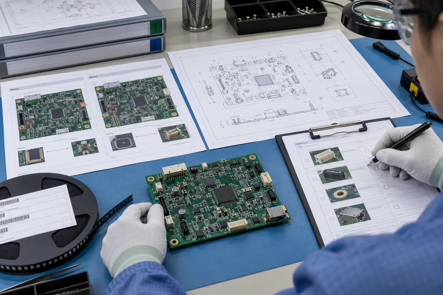
Match every manufacturing and test input to the build identifier before judging physical workmanship. Record the PCB part and revision, fabrication-data issue, BOM and approved manufacturer list, CPL/centroid file, assembly drawing, stencil or paste-data issue when controlled, machine program, approved substitution list, firmware or configuration ID, test instruction and limits. A board that passes a functional check against an unknown file set is not a usable first article.
| Input | Identity to record | Physical or digital cross-check | Stop condition |
|---|---|---|---|
| PCB | Part number, revision, panel/board identity | Outline, thickness or stack note when applicable, finish, markings, tooling and critical dimensions from the drawing | Board identity or required drawing feature does not match. |
| BOM / AVL | BOM issue, line, manufacturer and orderable part | Part marking, package, value, rating and approved alternate status | Unlisted substitute, ambiguous marking or wrong package. |
| CPL and assembly drawing | File issue or checksum and viewing convention | Reference designator, side, X/Y, rotation, pin 1, polarity and do-not-fit status | Source files disagree or orientation cannot be resolved. |
| Mechanical items | Drawing and hardware issue | Connector keying, height, seating, fastener, spacer, heat sink and keepout | Fit, orientation or hardware differs from the released definition. |
| Firmware and test | Image/configuration ID, test sequence and limit revision | Program verify result and named functional checks | Version is unknown or limits changed without a recorded decision. |
How should polarity, component direction, connectors and mechanical parts be checked?
Resolve each directional feature from a named source, then inspect the actual assembly at the same viewing orientation. Use the assembly drawing and component datasheet for diode bands, LED cathodes, electrolytic polarity, IC pin 1, transistor orientation and connector keying. Check CPL rotation only after confirming its coordinate and bottom-side convention. Silkscreen is a helpful visual cue, not the sole authority when it conflicts with released data.
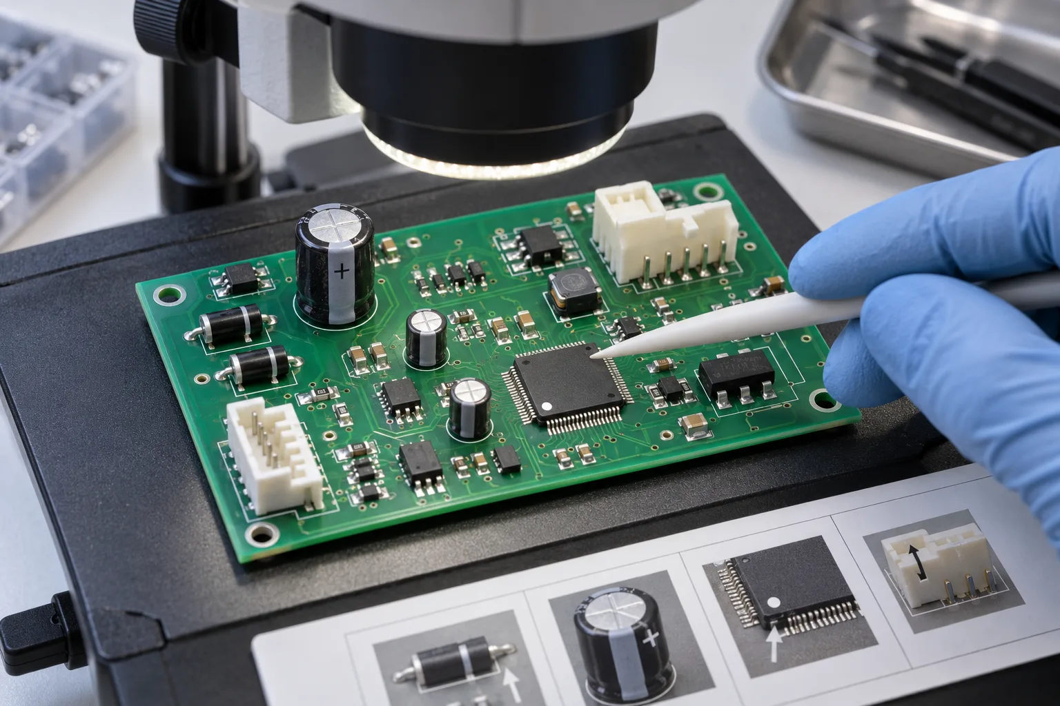
For connectors and mechanical parts, inspect more than presence. Record side, key direction, seating, coplanarity or insertion state as applicable, mating clearance, body height, latch access and any relationship to the enclosure or fixture. Where a dimension matters, name its drawing characteristic, method and result; do not use one invented universal tolerance.
How do dimensions, appearance, soldering, firmware and function become executable checks?
Write each row as requirement, source, method, result and disposition. “Check soldering” is not executable. “Inspect J4 pins to the agreed assembly-acceptance criteria; record pass/fail and image reference for any anomaly” is. A dimension row needs its drawing characteristic and measuring tool. A firmware row needs the expected image ID and verification method. A functional row needs stimulus, condition, measured response, unit and limit.
| Area | Check item | Method and record | Decision |
|---|---|---|---|
| Dimensions | Named board, connector or hardware characteristic from drawing | Record requirement, tool, actual value and unit | Pass only against the cited tolerance. |
| Appearance | Damage, contamination, marking, coating or hardware condition | Visual/magnified inspection with location and image reference for anomalies | Use the defined product/workmanship criterion. |
| Soldering | Selected joints, through-hole fill, polarity-sensitive and hidden-joint inspection plan | Record applicable acceptance source, method and result; use X-ray only where specified and suitable | Do not infer unobserved joints from a general visual pass. |
| Programming | Device, firmware/configuration ID and verify operation | Record file identifier/checksum, tool or station revision and verify result | Hold when the loaded version cannot be traced. |
| Critical function | Named power, communication, I/O or safety-related behavior | Record condition, stimulus, actual value/response and limit | A power-on light is not a substitute for defined functions. |
What should be measured on every first article?
Measure the characteristics that the drawing, product risk and pilot purpose identify as decision-critical; do not invent a universal list or sample quantity. Typical candidates include connector position and height, mounting-hole relationship, fitted hardware, controlled clearances and test-point access. The checklist should state why each characteristic matters and where its tolerance comes from.
How should deviations, substitutes, rework and open issues be recorded?
Keep them as separate, visible records linked to the affected unit and release decision. A substitute component needs the BOM line, original and proposed manufacturer part numbers, relevant difference and authorization reference. A deviation needs the unmet requirement, affected quantity or identities, temporary disposition, owner and expiry or closure condition. Rework needs the original defect, operation, material/process reference, operator or station, inspection and retest result.
An open issue may be compatible with a limited pilot continuation when its risk, containment, affected units and next decision are explicit. It cannot silently disappear behind “first article passed.” Mark the result as pass, conditional pass, hold or fail, and write exactly what each status authorizes.

What can a directly usable PCBA first-article checklist look like?
Use one header for configuration, one row per check and one section for exceptions and release. The following structure can be copied into a spreadsheet or inspection form and extended with product-specific characteristics.
Header: Project / PCBA ID [ ] | Unit or panel ID [ ] | PCB rev [ ] | BOM/AVL rev [ ] | CPL rev/checksum [ ] | Assembly drawing rev [ ] | Firmware/config ID [ ] | Test instruction/limits rev [ ] | Build date/route [ ].
Check row: Item no. [ ] | Characteristic or reference designator [ ] | Source requirement and revision [ ] | Method/tool [ ] | Expected result or limit [ ] | Actual result [ ] | Status [pass/fail/not run] | Evidence/reference [ ] | Inspector/date [ ].
Exception row: Type [deviation/substitute/rework/open issue] | Description [ ] | Affected unit/quantity [ ] | Authorization or procedure reference [ ] | Inspection/retest [ ] | Owner and closure date [ ] | Release effect [ ].
Disposition: [release / conditional release / hold / fail] | Configuration and quantity covered [ ] | Unclosed items [ ] | Decision owner/date [ ].
When should the first-article check be repeated?
Repeat the affected checks whenever a change can invalidate the evidence used for release. Triggers can include PCB or BOM revision, a new alternate, changed placement or inspection program, stencil or process-route change, line or tooling move, firmware/test-limit change, or correction of a failed first article. Record why a full or partial repeat is sufficient; do not treat the original pass as permanent.
Use the assembly drawing checklist to remove ambiguous orientation notes and the placement-data preflight to reconcile coordinates before the pilot build. For project-specific inspection and test planning, connect the completed checklist to PCB inspection and testing rather than submitting an RFQ from this guide.
About the author
PCBArise Electronics
PCBArise Electronics publishes this guide to help design and NPI teams prepare clearer manufacturing files. The requirements for any actual build are confirmed from its current design package.
FAQ
Common questions
Is PCBA first-article inspection the same as final inspection?+
No. First-article inspection checks the first identified assembly and its build setup before the pilot lot continues. Final inspection judges completed units or the shipment against the final acceptance plan. The two checkpoints have different timing, scope and evidence.
Does a PCBA first-article pass prove the design is reliable?+
No. It shows that the stated configuration met the recorded checks on the identified article. It does not prove long-term reliability, process capability, regulatory compliance, untested functions or conformance of every later unit.
What revisions belong on a PCBA first-article report?+
Record the PCB and fabrication-data issue, BOM/AVL, CPL or centroid data, assembly drawing, controlled stencil or machine program when relevant, approved deviations and substitutes, firmware/configuration, test instruction and limit revision.
How should component substitutions appear in the checklist?+
List the BOM line, original and substitute manufacturer part numbers, affected references, relevant electrical, package, marking, moisture or thermal differences, authorization reference and any added inspection or test. Never hide a substitute behind a general material-pass box.
How many boards are required for PCBA first-article inspection?+
There is no universal quantity for every PCBA. Define the first-article quantity from the purchase or quality requirement, panelization, product risk, build route and purpose of the pilot. State the exact unit or panel identities covered instead of borrowing an unsupported sample number.
Technical references
Sources used for this guide
These sources explain the standards, materials or process details discussed above. Check the current revision when applying them to a new design.
- Global Electronics Association — rigid printed-board assembly process checklist
- SAE AS9102C — formal aerospace FAI scope and documentation boundary
- NASA workshop — printed-circuit-board inspection and quality-control context
- PCBA Partner — pilot-lot first-article configuration and release checks
- XFPCB — first-piece setup, polarity and inspection records
- Elecrow — risk-based PCBA first-article verification
- Global Electronics Association — 2026 standards work on assembly, inspection and traceability