
SMT sides and THT access
Map component side, height, weight, thermal limits and solder access so later operations do not disturb previously formed joints.
Mixed technology PCB assembly combines surface-mount placement with through-hole, press-fit, odd-form or hand operations. The process succeeds when every thermal and mechanical step is sequenced around the released board, component mix and acceptance plan.
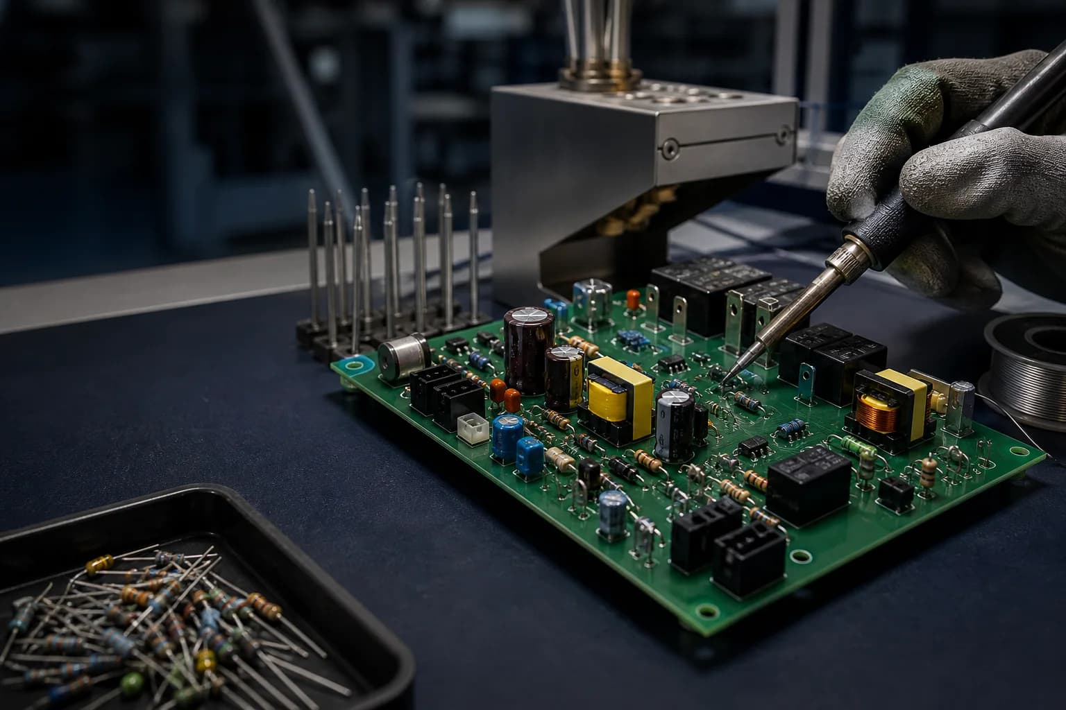
A mixed-technology assembly contains more than one component or connection route. It may combine top- and bottom-side SMT, through-hole connectors, press-fit contacts, transformers, relays, hardware, cable interfaces or parts that require controlled hand operations. The correct route is not simply “SMT first, THT second”; it is a documented sequence that protects earlier joints and sensitive components during every later step. PCBArise already publishes SMT, THT/DIP, BGA, QFN, press-fit and odd-form scope within its assembly capability reference. This page turns those individual capabilities into a commercial service decision: which files are needed, how soldering methods are chosen, what must be reviewed before quotation and what evidence should follow the finished build.
Every additional soldering or mechanical operation can change board support, thermal exposure, component clearance and inspection access. The sequence should be designed as one system.
Map component side, height, weight, thermal limits and solder access so later operations do not disturb previously formed joints.
Choose the method from keep-outs, connector geometry, board mass, underside population, alloy and workmanship requirements.
Define tooling, force, support, orientation, hardware and inspection requirements for parts outside automated placement.
Place inspection and testing where failures can still be detected and corrected without assuming the final visual check covers the whole route.
Use this reference to prepare a credible quotation package. Final sequence, method, fixtures, line assignment and acceptance evidence remain project-specific.
Final scope, limits and evidence are confirmed from the released build package.
| Required quote package | Gerber or ODB++, BOM, CPL/centroid data, assembly drawing, mechanical drawings and available programming or test requirements. |
|---|---|
| Component classification | SMT, through-hole, press-fit, odd-form, hardware and manual-install items identified by reference designator and side. |
| SMT sequence | Top- and bottom-side print, placement and reflow reviewed with package weight, adhesive needs, board support and later solder exposure. |
| Through-hole route | Wave, selective or hand soldering selected from component geometry, underside keep-outs, thermal mass and required workmanship. |
| Press-fit operations | Connector, compliant-pin, insertion force, tooling, backing support and verification defined from approved component data. |
| Odd-form handling | Orientation, lead forming, clinching, fastening, adhesive, clearance and manual or automated handling requirements documented. |
| Board support | Panel rails, pallets, carriers, tooling holes, fiducials and underside clearance reviewed for every thermal and insertion step. |
| Process protection | Masking, heat shields, temporary fixtures or sequencing used only when the released design and process review require them. |
| Inspection plan | SPI, AOI, X-ray and visual methods placed where each can observe the intended feature or joint. |
| Test and programming | ICT, flying probe, firmware loading and functional testing included when procedures, files, fixtures and limits are available. |
The exact flow changes by design; these stages show the decisions that must be closed rather than prescribing one universal recipe.
| 1. File and revision review | Reconcile fabrication data, BOM, CPL, drawings, mechanical information and no-fit instructions. |
|---|---|
| 2. Material and tooling plan | Confirm package, board, stencil, pallet, carrier, insertion tool, fixture and handling requirements. |
| 3. SMT operations | Run the approved print, placement and reflow sequence for each populated side. |
| 4. THT and mechanical operations | Insert, press-fit, fasten or form components using the selected support and process controls. |
| 5. Secondary soldering | Apply wave, selective or hand soldering where access and thermal constraints support the method. |
| 6. Inspection and cleaning | Use the approved visual, automated, X-ray and cleanliness evidence at the relevant checkpoints. |
| 7. Programming and test | Execute the released firmware and electrical or functional procedures with defined limits and records. |
A surface-mount section may pass AOI and still be damaged during a later insertion, selective-solder or manual operation. Mixed assembly planning therefore connects thermal exposure, mechanical force, access and inspection checkpoints. Compare the foundation on SMT Assembly and Through-Hole Assembly, then use the mixed route to resolve their interfaces.
The final process plan should make ownership, sequence, tooling and evidence visible before a mixed build enters production.
Use the route when automated placement and mechanically robust or high-power connections must coexist on the same released assembly.
Combine dense control electronics with terminal blocks, relays, connectors and serviceable through-hole interfaces.
Coordinate large thermal masses, power devices, magnetics, bus connections and control-side SMT populations.
Connect high-density packages, robust connectors and project-specific inspection or test evidence.
Integrate precision SMT circuits with connectors, mechanical controls and defined calibration or functional checks.
Place hidden-joint packages within a route that also includes connectors, press-fit or secondary soldering.
Capture first-build learning in tooling, sequence, workmanship and test records before scaling.
Use these answers to define the process route without assuming all mixed assemblies follow one fixed sequence.
A mixed assembly combines process families such as SMT and through-hole, or adds press-fit, odd-form, hardware and controlled manual operations. The defining feature is the need to coordinate their sequence and interfaces.
Often, but not unconditionally. Side population, component weight, adhesive, solder access, thermal limits, carriers and later mechanical operations can change the approved sequence.
The decision depends on component and lead geometry, underside keep-outs, board thermal mass, alloy, access, quantity, workmanship requirements and the evidence needed for acceptance.
They can be evaluated as part of the SMT route. The BGA land pattern, print, reflow and hidden-joint inspection plan must remain compatible with the THT and secondary operations that follow.
Provide approved component data, assembly and mechanical drawings, orientation, insertion or fastening requirements, tooling information and inspection or test criteria in addition to the standard PCB assembly package.
Use the connected pages to resolve surface-mount, through-hole, BGA and acceptance decisions before release.
Share the released PCB files, BOM, CPL, assembly and mechanical drawings, plus programming and test requirements so every SMT, THT and secondary operation can be reviewed together.