
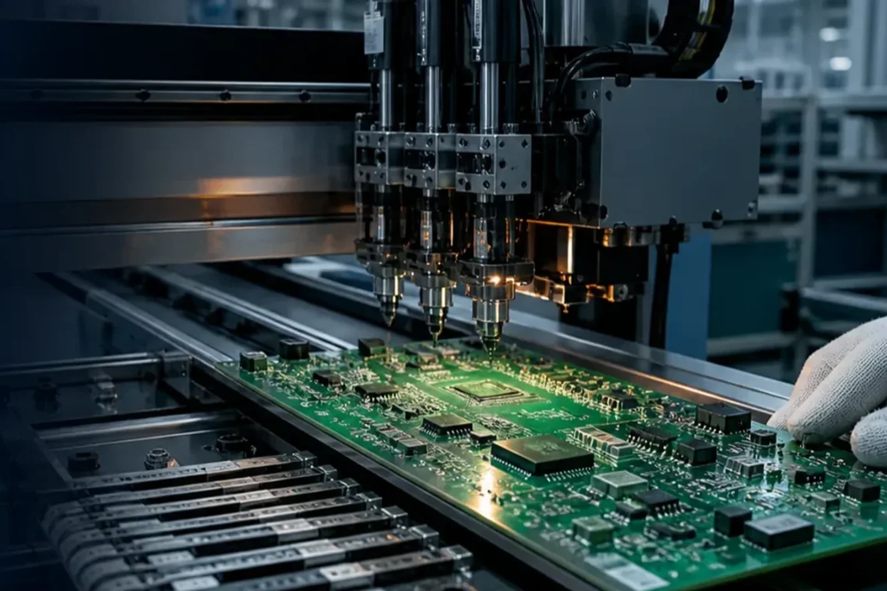
Decision map
From requirement to controlled release.
Resolve the project in this order so the supplier is not forced to infer scope from disconnected files.
Start with the difference between PCB and PCBA.
A PCB is the bare fabricated board: laminate, copper features, holes, solder mask, legend and surface finish. A PCBA is that board after components are placed, soldered and inspected. The distinction changes the files, quotation assumptions, lead-time drivers and acceptance evidence.
If the order is for assembled boards, define both fabrication and assembly requirements. A correct bare board does not prove the component population, programming or product function, while assembly inspection cannot compensate for an incorrect stackup or footprint.
Fabrication data
Gerber or ODB++, fabrication drawing, stackup, materials, finish and electrical-test requirements.
Assembly data
BOM, CPL/centroid data, assembly drawing, approved variants, programming and test requirements.
System evidence
Enclosure interfaces, cable or box-build instructions, functional procedure, limits and shipment configuration.
Build one revision-controlled quotation package.
The fastest route to a defensible quotation is not the smallest upload. It is one package in which design revision, quantities, component identity and acceptance requirements agree. Include a short README that lists the released revision and any open decisions.
PCBA quotation package
Minimum working inputs and the question each one closes.
| Fabrication data | Gerber or ODB++, drill files, stackup and fabrication drawing define the bare-board baseline. |
|---|---|
| BOM | Manufacturer part number, quantity, reference designators, package, do-not-fit status and approved alternates. |
| CPL / centroid | Reference designator, X/Y position, rotation, side and board origin for placement programming. |
| Assembly drawing | Polarity, orientation, special process notes, hardware, no-fit items and revision. |
| Test package | Procedure, fixtures, software, limits, test points, sample or 100% coverage, and required records. |
| Commercial scope | Order quantity, forecast, sourcing responsibility, target date, shipment and packaging requirements. |
Match SMT, through-hole and mixed technology to the component set.
SMT supports dense, automated placement and reflow. Through-hole supports leaded parts that require mechanical retention, power handling or a package unavailable in SMT. Mixed-technology boards need a defined sequence because later soldering, cleaning, inspection and rework can affect earlier operations.
Print → place → reflow
Review stencil, paste, package handling, placement data, thermal mass and visible inspection.
Insert → solder → trim
Choose wave, selective or controlled hand soldering from board layout, clearances and component sensitivity.
Hidden joints
Connect land pattern, via treatment, stencil, profile and X-ray coverage to defined acceptance criteria.
Choose turnkey, consigned or partial-turnkey sourcing deliberately.
The sourcing model assigns responsibility; it does not remove it. Turnkey puts procurement and coordination with the assembler. Consigned places component supply with the customer. Partial-turnkey splits the BOM. In every model, approved part identity, substitutes, excess material, shortages, traceability and customer approval rules need to be explicit.
Sourcing model comparison
Use the model that makes ownership and approval boundaries easiest to control.
| Turnkey | Supplier sources the approved BOM and coordinates material with fabrication, assembly and agreed test. |
|---|---|
| Consigned | Customer supplies components; receiving, count, condition, moisture handling and shortage rules must be agreed. |
| Partial turnkey | Customer supplies selected constrained or programmed parts; supplier sources the remaining approved lines. |
| Alternates | No substitution should be automatic. Record the proposed part, technical impact and required approval. |
Separate prototype learning from production release.
Prototype builds expose footprint, orientation, manufacturability and test questions. NPI or pilot builds should close those findings under a stable revision. Volume production then needs material continuity, repeatable process controls, change notification and the records required for each lot.
Learn
Make open assumptions visible and capture deviations, manual operations and design feedback.
Stabilize
Validate released data, work instructions, process evidence, test coverage and packaging.
Repeat
Control approved revisions, alternates, traceability, capacity, sampling and change approval.
Select inspection and testing by failure mode.
No single method proves the complete assembly. SPI evaluates solder-paste deposition; AOI evaluates visible placement and solder features; X-ray examines hidden joints; ICT or flying probe evaluates electrical networks; functional test exercises defined product behavior. Coverage should follow the package geometry, test access, risk and acceptance criteria.
Inspection and test roles
Define what each method is expected to detect before requesting evidence.
| SPI | Paste volume, area, height and print alignment before placement. |
|---|---|
| AOI | Visible component presence, polarity, alignment and solder-feature conditions. |
| X-ray / AXI | Hidden-joint conditions, bridging, opens, voiding or internal features within the approved plan. |
| ICT / flying probe | Net connectivity and component-level electrical checks where design access supports them. |
| Functional test | Product functions under an approved procedure, fixtures, software, limits and configuration. |
Treat programming, coating and box build as controlled operations.
Secondary operations often introduce the last revision, handling and acceptance risks. Firmware needs an approved binary, version identity and verification method. Conformal coating needs masking, material and cure criteria. Box build needs mechanical drawings, cable maps, torque or label instructions and a finished-product test boundary.
- Identify firmware file, checksum or version, target device and programming stage.
- Define coating keep-outs, thickness or coverage criteria, cure and inspection.
- List hardware, cables, labels, enclosure revisions and mechanical acceptance points.
- State whether final testing covers only the PCBA or the assembled product.
Control cost and lead time through complete decisions.
PCBA cost is shaped by bare-board complexity, component price and availability, placement count, package risk, setup, inspection, test, secondary operations, yield and order pattern. Lead time can be dominated by a single constrained component or an unresolved engineering question.
- Freeze the production revision and identify acceptable variants before purchasing.
- Separate one-time tooling, programming or fixture charges from recurring unit cost.
- Ask which materials or approvals control the quoted schedule.
- Compare quotations on assumptions and evidence, not unit price alone.
Common risks to close before production.
Use these as review prompts. The project-specific decision still follows the released design, build route and acceptance requirements.
- BOM, Gerber, CPL and assembly drawing identify different revisions.
- A substitute component is purchased without the agreed customer approval.
- Centroid rotation or board origin is interpreted differently by design and assembly.
- Hidden-joint inspection is requested without defined coverage or acceptance criteria.
- Prototype deviations are carried into volume production without formal closure.
- Programming, fixtures, labels or packaging are discovered after material commitment.